Achievable logoAchievable logo
CCNA
Sign in
Sign up
Purchase
Textbook
Practice exams
Support
How it works
Exam catalog
Mountain with a flag at the peak
Textbook
Introduction
1. Introduction to networking
1.1 What is networking?
1.2 Components of a TCP/IP based network
1.3 How devices communicate on a TCP/IP based network
1.4 The layers of the TCP/IP model
1.5 Introduction to the Transport Layer
1.6 Introduction to network architecture
1.6.1 Network topology architectures
1.6.2 On-premise vs. the cloud and virtualization
2. Administering Ethernet LANs
3. IP connectivity
4. Network services
5. IPv6
6. Wireless networking
7. Network management and administering network devices
8. Network security fundamentals
9. Network automation and programmability
Wrapping up
Achievable logoAchievable logo
1.6.1 Network topology architectures
Achievable CCNA
1. Introduction to networking
1.6. Introduction to network architecture
Our CCNA course is currently in development and is a work-in-progress.

Network topology architectures

9 min read
Font
Discuss
Share
Feedback

Various network topology architectures

Networks come in many designs and connectivity models. The right design depends on two main things:

  • Scale (small, medium, or large)
  • Purpose (home office, enterprise/campus, data center, or service provider) As a network engineer (and a CCNA candidate), you’ll want to recognize these common topology architectures and understand why each one is used.

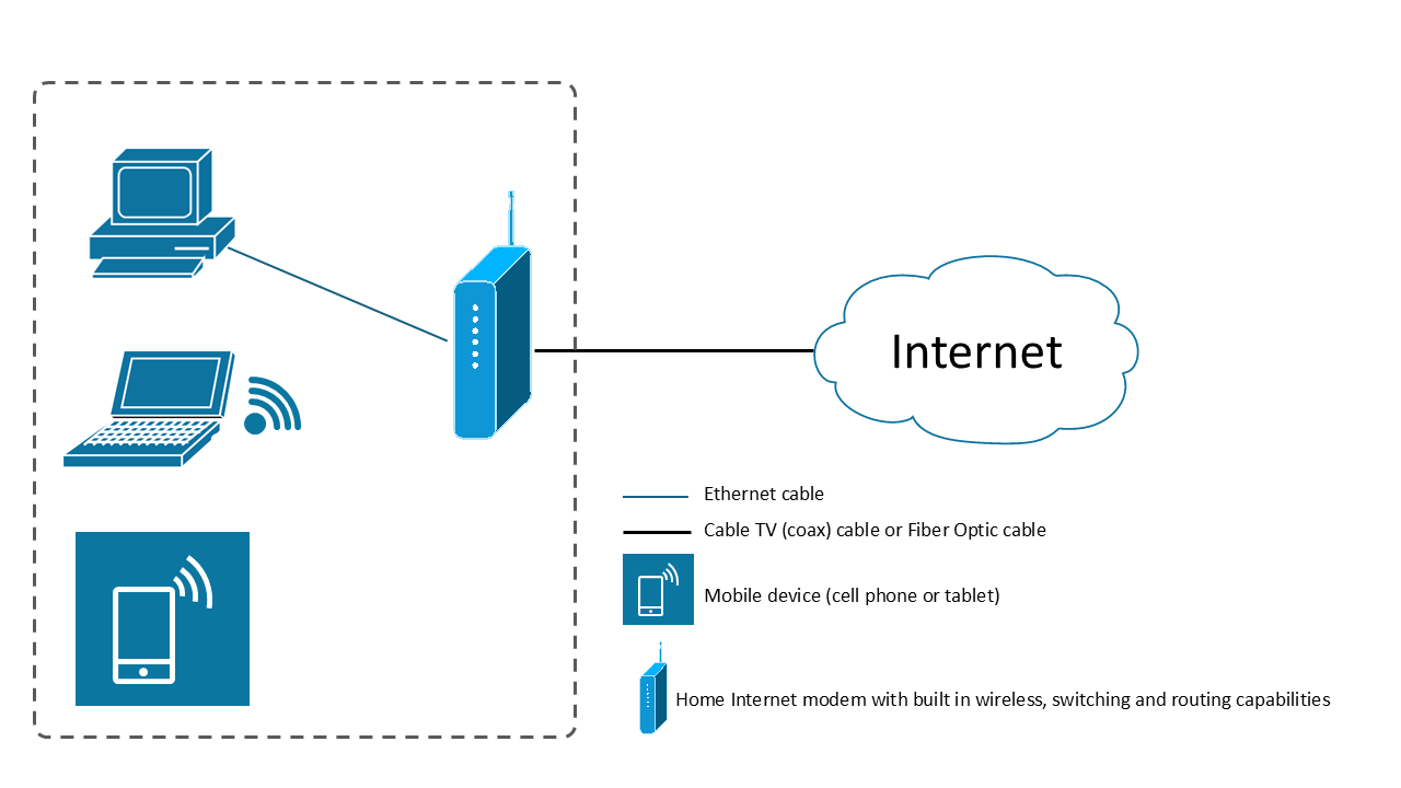
Small office/home office (SOHO) networks

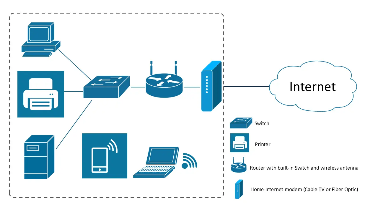
Most people are already familiar with the small office/home office (SOHO) network type. If you have internet at home, you already have a SOHO-style network. A typical SOHO network includes:

  • Endpoints (PCs, laptops, phones, TVs)
  • A wired router with a built-in switch, or a wireless router/wireless access point
  • A cable modem or fiber optic modem (depending on your internet service) It’s also common for the modem to include routing and switching features (an “all-in-one” device).
    Small office and home office network topology with connected devices and ro
    SOHO network
    If a home office has more devices than the built-in switch can support, you’ll often see an additional switch added for more wired ports. For wireless coverage, you may also see wireless extenders or additional wireless access points placed around the home to extend coverage. This same general design is also common in small branch offices, where keeping costs low matters. These offices often use lower-end switches throughout the space that connect back to a single router, which then connects to broadband internet (cable or consumer-grade fiber). To support more users and applications, these sites often pay for:
  • More bandwidth
  • Higher speeds to support more throughput (the amount/rate of traffic that can pass through a network over time)
    Small office network layout
    Small office

Enterprise (Campus) networks

The next topology architecture is commonly used in medium to large businesses (often called enterprises). These organizations may have multiple buildings in close geographic proximity, with their office networks interconnected. That’s why these are called campus networks - the design is similar to a college campus. As enterprise networks grow, they’re often built in tiers (also called layers). Each layer has devices with specific roles, which helps the network stay efficient, resilient, and easier to manage. Enterprise campus networks typically require more resiliency and redundancy than SOHO networks. Downtime is expensive, so these networks usually use enterprise-grade equipment designed for heavy usage and high reliability. You’ll also see redundant devices and links to support business continuity if a device or connection fails.

Two-tier (Collapsed Core) network architecture

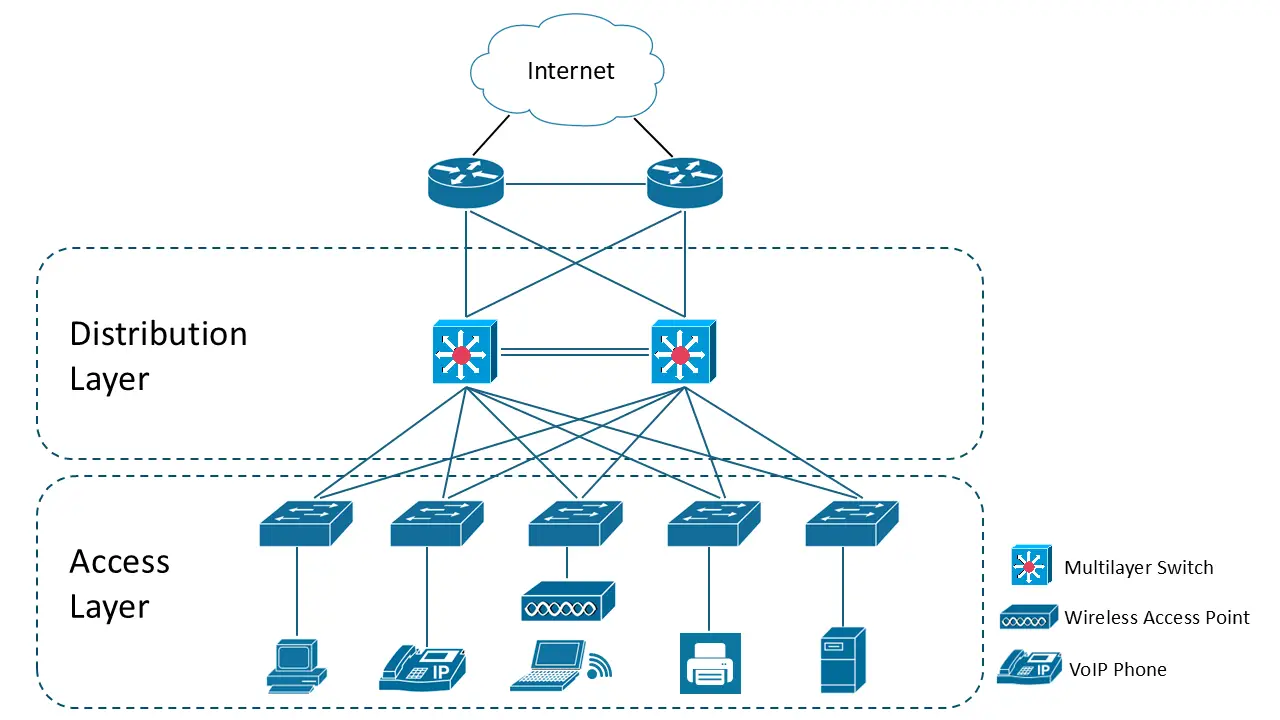
For many small to medium enterprise networks, a two-tier architecture is enough. This topology has two layers:

  • Access layer
  • Distribution layer
    Two-tier collapsed core network architecture
    Two-tier (Collapsed Core)
     

Access Layer

The Access Layer is where endpoints connect to the network. This is where you’ll find switches that connect:

  • Endpoints
  • Servers
  • Wireless access points Wireless endpoints connect to the wireless access points, and those access points are hardwired into the Access Layer switches.

It is important to understand that these Access Layer Switches will be racked and installed within the IT closets (commonly known in the field as Intermediate Distribution Frames or “IDFs”) throughout each floor of the building or office where endpoints need to connect.

Distribution Layer

The Distribution Layer sits above the Access Layer. It typically contains a pair of switches that all Access Layer switches connect into. Key ideas in this layer:

  • There are usually two distribution switches for redundancy.
  • Access switches often have redundant uplinks (more than one) to the distribution switches.
  • If one uplink fails or is disconnected, traffic can continue over the remaining uplink.

Sidenote
Explanation of a link/uplink

A “link” is a connection via a cable between an endpoint and a network device or to connect network devices to each other. An “uplink” is the cable that connects a network device in a lower layer to a network device in a higher layer of a network topology.

The Distribution Layer is used to enforce traffic flow policies. It also functions as a central aggregation point for the Access Layer.

It’s very important to note that Access Layers Switches should never be connected (or “daisy-chained”) together using their front-panel Ethernet ports in an enterprise network design, as that can lead to network traffic taking a sub-optimal path that can lead to high latency (slowness) and bottlenecks in the network.

Two access switches connected in a daisy-chain configuration
Improperly connected (daisy-chained) Access Switches
Distribution switches are typically higher-end switches with:

  • More switching capacity
  • Higher throughput and bandwidth
  • More features than standard access switches They also commonly provide routing between IP networks across the campus. That’s why the Distribution Layer often uses Layer 3 (or multi-layer) switches. To reach the internet, distribution switches usually have redundant uplinks to a redundant pair of routers. Those routers provide:
  • Internet access
  • Connectivity to other organizational sites (regional, national, or global) Even though Layer 3 switches can route, routers are still used because they often provide more robust routing features needed for internet and WAN connectivity. Depending on the organization, these routers may be owned by the enterprise or provided/managed by the ISP. This two-tier design is also called a collapsed core design. In many medium-sized enterprises, there’s no need for a dedicated Core Layer, so the Distribution Layer effectively performs both distribution and core functions to reduce cost and hardware.

Three-tier network architecture

Enterprise network divided into core, distribution, and access layers
Three-tier network architecture
A three-tier topology keeps the same Access and Distribution Layers, but adds a third layer: the Core Layer.

  • The Distribution Layer uplinks to a pair of Layer 3 switches in the Core Layer.
  • This design is typically used in large enterprise campus networks. It’s especially useful when you have three or more buildings or multiple geographically dispersed sites. Without a Core Layer, you may end up connecting distribution blocks to each other in a full mesh, which doesn’t scale well.
    Distribution switches connected in a full mesh topology
    Distribution blocks in a full mesh
      In a full-mesh distribution design, the number of links grows quickly as you add more buildings and distribution switches. That increases complexity and cost. It can be especially expensive if buildings must be connected using service-provider fiber. With a Core Layer:
  • Each distribution block connects to the core switches.
  • You avoid connecting every distribution block to every other distribution block.
  • Each distribution block typically needs only two uplinks to the core, while still avoiding single points of failure. The Core Layer is designed for high-speed, high-capacity routing between IP networks across the enterprise. Core switches are often located in the organization’s headquarters or in the data center.
    Campus network layout showing a centralized core layer connecting multiple network sections
    Proper campus design with a core layer
      In a three-tier architecture, the core switches connect to a redundant pair of routers, either owned/managed by the organization or provided by a service provider.

One of the main goals of the Core Layer is to provide high speed, uninterrupted routing. This is why you typically will not see a lot of security or traffic policies or restrictions at this layer.

Small office/home office (SOHO) networks

  • Designed for small scale and cost efficiency
  • Components: endpoints, wired/wireless router, modem (often all-in-one)
  • Expansion: add switches for more ports, wireless extenders for coverage

Enterprise (Campus) networks

  • Used in medium/large businesses with multiple buildings
  • Built in tiers/layers for efficiency and manageability
  • Emphasize resiliency, redundancy, and enterprise-grade equipment

Two-tier (Collapsed Core) network architecture

  • Layers: Access (endpoints, servers, WAPs) and Distribution (aggregation, policy enforcement)
  • Access layer: switches in IDFs, connect endpoints and WAPs
  • Distribution layer: typically two switches for redundancy, Layer 3/multi-layer switches, uplinks to routers for internet/WAN

Three-tier network architecture

  • Adds Core Layer above Distribution and Access
  • Core Layer: high-speed routing, connects distribution blocks, reduces full mesh complexity
  • Used in large enterprises with multiple buildings/sites

Spine/Leaf architecture

  • Used in data centers for scalability and low latency
  • Two layers: Leaf (connects servers/endpoints), Spine (connects all leafs, no spine-to-spine or leaf-to-leaf)
  • Highly scalable: add leafs for endpoints, spines for capacity; always two hops between leafs

Wide Area Network (WAN)

  • Connects geographically dispersed sites via routers
  • Types:
    • Point-to-Point: direct link between two sites
    • Hub-and-Spoke (Point-to-Multipoint): branches connect to central hub(s), cost-effective but adds latency
    • Full Mesh: every site connects to every other, maximizes redundancy but costly
  • WAN Core: central routing infrastructure
  • Private WANs: owned/managed by organization, high uptime, costly
  • Public WANs: e.g., the Internet, best-effort delivery, less secure
    • VPNs used to secure data over public WANs

Sign up for free to take 10 quiz questions on this topic

Previous
Next  | 1.6.2 On-premise vs. the cloud and virtualization
All rights reserved ©2016 - 2026 Achievable, Inc.

Network topology architectures

Various network topology architectures

Networks come in many designs and connectivity models. The right design depends on two main things:

  • Scale (small, medium, or large)
  • Purpose (home office, enterprise/campus, data center, or service provider) As a network engineer (and a CCNA candidate), you’ll want to recognize these common topology architectures and understand why each one is used.

Small office/home office (SOHO) networks

Most people are already familiar with the small office/home office (SOHO) network type. If you have internet at home, you already have a SOHO-style network. A typical SOHO network includes:

  • Endpoints (PCs, laptops, phones, TVs)
  • A wired router with a built-in switch, or a wireless router/wireless access point
  • A cable modem or fiber optic modem (depending on your internet service) It’s also common for the modem to include routing and switching features (an “all-in-one” device). If a home office has more devices than the built-in switch can support, you’ll often see an additional switch added for more wired ports. For wireless coverage, you may also see wireless extenders or additional wireless access points placed around the home to extend coverage. This same general design is also common in small branch offices, where keeping costs low matters. These offices often use lower-end switches throughout the space that connect back to a single router, which then connects to broadband internet (cable or consumer-grade fiber). To support more users and applications, these sites often pay for:
  • More bandwidth
  • Higher speeds to support more throughput (the amount/rate of traffic that can pass through a network over time)

Enterprise (Campus) networks

The next topology architecture is commonly used in medium to large businesses (often called enterprises). These organizations may have multiple buildings in close geographic proximity, with their office networks interconnected. That’s why these are called campus networks - the design is similar to a college campus. As enterprise networks grow, they’re often built in tiers (also called layers). Each layer has devices with specific roles, which helps the network stay efficient, resilient, and easier to manage. Enterprise campus networks typically require more resiliency and redundancy than SOHO networks. Downtime is expensive, so these networks usually use enterprise-grade equipment designed for heavy usage and high reliability. You’ll also see redundant devices and links to support business continuity if a device or connection fails.

Two-tier (Collapsed Core) network architecture

For many small to medium enterprise networks, a two-tier architecture is enough. This topology has two layers:

  • Access layer
  • Distribution layer  

Access Layer

The Access Layer is where endpoints connect to the network. This is where you’ll find switches that connect:

  • Endpoints
  • Servers
  • Wireless access points Wireless endpoints connect to the wireless access points, and those access points are hardwired into the Access Layer switches.

It is important to understand that these Access Layer Switches will be racked and installed within the IT closets (commonly known in the field as Intermediate Distribution Frames or “IDFs”) throughout each floor of the building or office where endpoints need to connect.

Distribution Layer

The Distribution Layer sits above the Access Layer. It typically contains a pair of switches that all Access Layer switches connect into. Key ideas in this layer:

  • There are usually two distribution switches for redundancy.
  • Access switches often have redundant uplinks (more than one) to the distribution switches.
  • If one uplink fails or is disconnected, traffic can continue over the remaining uplink.
Sidenote
Explanation of a link/uplink

A “link” is a connection via a cable between an endpoint and a network device or to connect network devices to each other. An “uplink” is the cable that connects a network device in a lower layer to a network device in a higher layer of a network topology.

The Distribution Layer is used to enforce traffic flow policies. It also functions as a central aggregation point for the Access Layer.

It’s very important to note that Access Layers Switches should never be connected (or “daisy-chained”) together using their front-panel Ethernet ports in an enterprise network design, as that can lead to network traffic taking a sub-optimal path that can lead to high latency (slowness) and bottlenecks in the network. Distribution switches are typically higher-end switches with:

  • More switching capacity
  • Higher throughput and bandwidth
  • More features than standard access switches They also commonly provide routing between IP networks across the campus. That’s why the Distribution Layer often uses Layer 3 (or multi-layer) switches. To reach the internet, distribution switches usually have redundant uplinks to a redundant pair of routers. Those routers provide:
  • Internet access
  • Connectivity to other organizational sites (regional, national, or global) Even though Layer 3 switches can route, routers are still used because they often provide more robust routing features needed for internet and WAN connectivity. Depending on the organization, these routers may be owned by the enterprise or provided/managed by the ISP. This two-tier design is also called a collapsed core design. In many medium-sized enterprises, there’s no need for a dedicated Core Layer, so the Distribution Layer effectively performs both distribution and core functions to reduce cost and hardware.

Three-tier network architecture

A three-tier topology keeps the same Access and Distribution Layers, but adds a third layer: the Core Layer.

  • The Distribution Layer uplinks to a pair of Layer 3 switches in the Core Layer.
  • This design is typically used in large enterprise campus networks. It’s especially useful when you have three or more buildings or multiple geographically dispersed sites. Without a Core Layer, you may end up connecting distribution blocks to each other in a full mesh, which doesn’t scale well.   In a full-mesh distribution design, the number of links grows quickly as you add more buildings and distribution switches. That increases complexity and cost. It can be especially expensive if buildings must be connected using service-provider fiber. With a Core Layer:
  • Each distribution block connects to the core switches.
  • You avoid connecting every distribution block to every other distribution block.
  • Each distribution block typically needs only two uplinks to the core, while still avoiding single points of failure. The Core Layer is designed for high-speed, high-capacity routing between IP networks across the enterprise. Core switches are often located in the organization’s headquarters or in the data center.   In a three-tier architecture, the core switches connect to a redundant pair of routers, either owned/managed by the organization or provided by a service provider.

One of the main goals of the Core Layer is to provide high speed, uninterrupted routing. This is why you typically will not see a lot of security or traffic policies or restrictions at this layer.

Key points

Small office/home office (SOHO) networks

  • Designed for small scale and cost efficiency
  • Components: endpoints, wired/wireless router, modem (often all-in-one)
  • Expansion: add switches for more ports, wireless extenders for coverage

Enterprise (Campus) networks

  • Used in medium/large businesses with multiple buildings
  • Built in tiers/layers for efficiency and manageability
  • Emphasize resiliency, redundancy, and enterprise-grade equipment

Two-tier (Collapsed Core) network architecture

  • Layers: Access (endpoints, servers, WAPs) and Distribution (aggregation, policy enforcement)
  • Access layer: switches in IDFs, connect endpoints and WAPs
  • Distribution layer: typically two switches for redundancy, Layer 3/multi-layer switches, uplinks to routers for internet/WAN

Three-tier network architecture

  • Adds Core Layer above Distribution and Access
  • Core Layer: high-speed routing, connects distribution blocks, reduces full mesh complexity
  • Used in large enterprises with multiple buildings/sites

Spine/Leaf architecture

  • Used in data centers for scalability and low latency
  • Two layers: Leaf (connects servers/endpoints), Spine (connects all leafs, no spine-to-spine or leaf-to-leaf)
  • Highly scalable: add leafs for endpoints, spines for capacity; always two hops between leafs

Wide Area Network (WAN)

  • Connects geographically dispersed sites via routers
  • Types:
    • Point-to-Point: direct link between two sites
    • Hub-and-Spoke (Point-to-Multipoint): branches connect to central hub(s), cost-effective but adds latency
    • Full Mesh: every site connects to every other, maximizes redundancy but costly
  • WAN Core: central routing infrastructure
  • Private WANs: owned/managed by organization, high uptime, costly
  • Public WANs: e.g., the Internet, best-effort delivery, less secure
    • VPNs used to secure data over public WANs

More from Introduction to network architecture

  • On-premise vs. the cloud and virtualization