


Achievable logoAchievable logo
CCNA
Sign in
Sign up
Purchase
Textbook
Practice exams
Support
How it works
Exam catalog
Mountain with a flag at the peak
Textbook
Introduction
1. Introduction to networking
1.1 What is networking?
1.2 Components of a TCP/IP based network
1.3 How devices communicate on a TCP/IP based network
1.4 The layers of the TCP/IP model
1.5 Introduction to the Transport Layer
1.6 Introduction to network architecture
2. Administering Ethernet LANs
3. IP connectivity
4. Network services
5. IPv6
6. Wireless networking
7. Network management and administering network devices
8. Network security fundamentals
9. Network automation and programmability
Wrapping up
Achievable logoAchievable logo
1.4 The layers of the TCP/IP model
Achievable CCNA
1. Introduction to networking
Our CCNA course is currently in development and is a work-in-progress.

The layers of the TCP/IP model

10 min read
Font
Discuss
Share
Feedback

As you saw on the first page of this book (Chapter 1.1 What is networking?), the networks we use today are based on the TCP/IP model. To understand how one computer exchanges data with another, you first need a clear picture of what the TCP/IP model is and what each layer does.

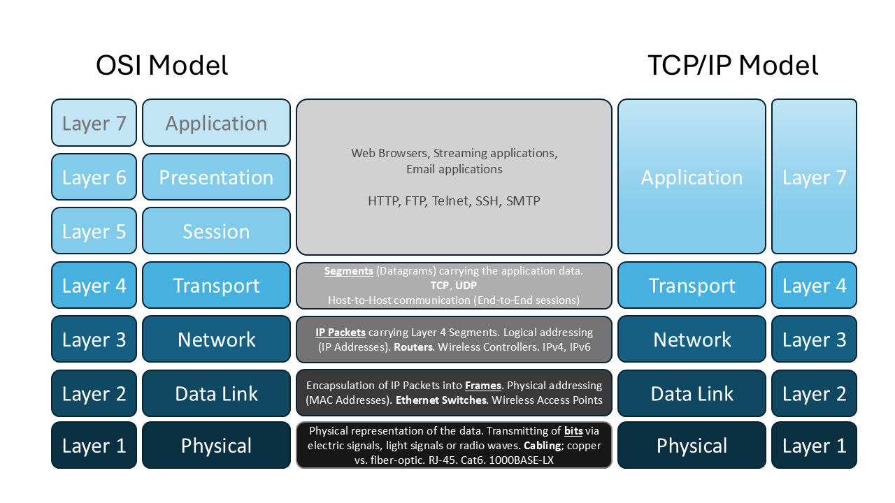
Comparison of the OSI and TCP/IP models and their layers
OSI model vs. the TCP/IP model

TCP/IP model

The TCP/IP model is based on an older networking framework called the OSI (Open Systems Interconnection) model. Both models organize networking technologies and protocols into layers that work together to deliver data from one endpoint to another.

  • The OSI model has seven layers.
  • The TCP/IP model is a more modern, condensed version with five layers.

You’ll also see people casually refer to the TCP/IP model as the “OSI model.” What they usually mean is that the TCP/IP model maps closely to OSI concepts and is commonly used in real-world networking.

A helpful way to think about layers is to compare them to building a house. Different specialists handle different parts of the job:

  • One team lays the foundation.
  • Another builds the frame.
  • Others install plumbing and electrical.

Each step depends on the earlier steps. You can’t install windows without walls, and you can’t finish a kitchen without plumbing. Networking layers work the same way: each layer relies on the services of the layer below it.

A concrete example makes this easier to see.

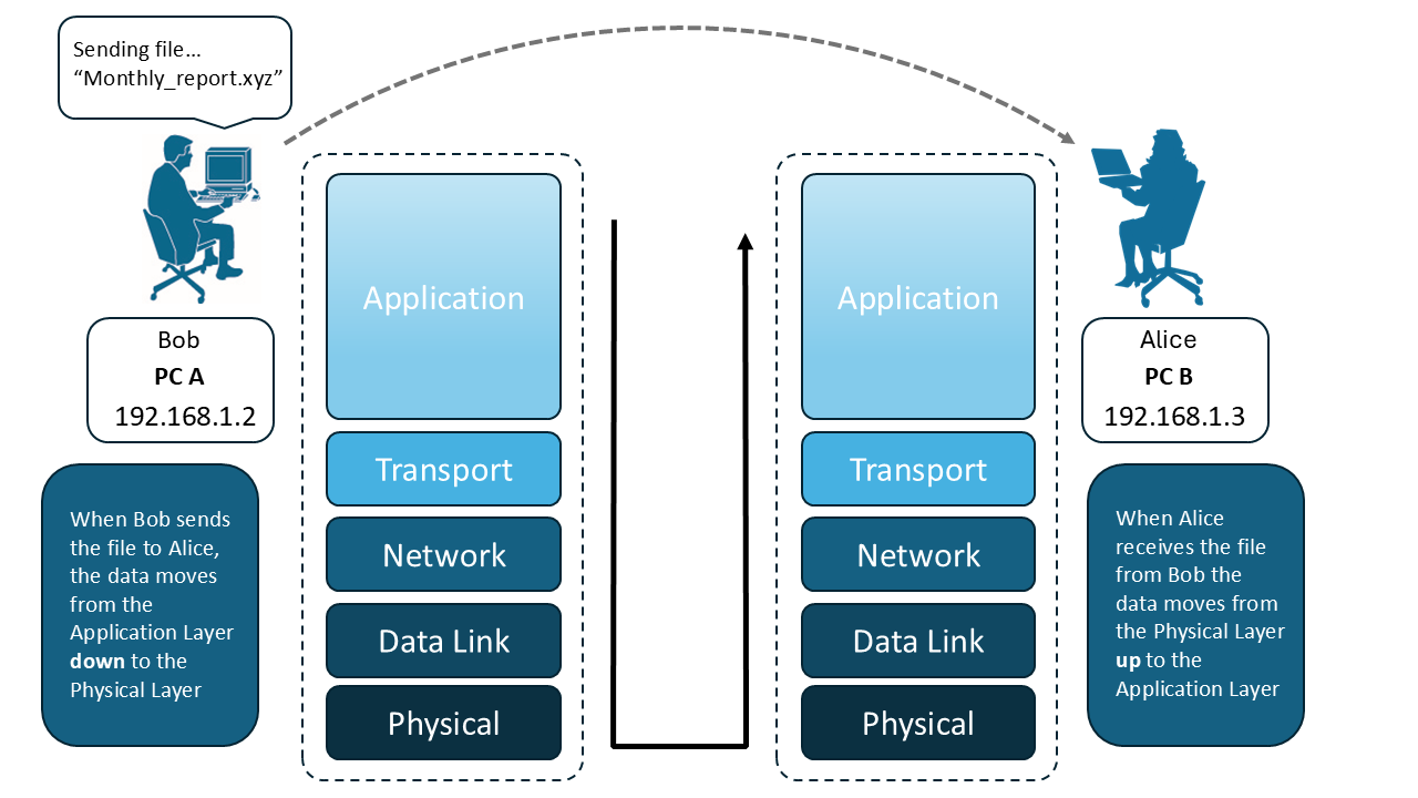
PC A sending data packets to PC B across a network connection
PC A sending data to PC B
Say PC A wants to send a file to PC B. We’ll walk through what happens at each layer of the TCP/IP model.

When troubleshooting, you typically start at the bottom (Physical) and work upward. For learning how data is created and prepared to be sent, it’s clearer to start at the top (Application) and work downward.

  • Application Layer: PC A is running an application called the “XYZ App.” It wants to send a file to PC B, which is running the same app and will process the file. The XYZ App prepares the file for transmission, often by breaking it into smaller pieces that can be sent efficiently. Because this is a TCP-based application, it hands the data to TCP on the computer.

  • Transport Layer: This layer uses either TCP or UDP to split the data into smaller, manageable pieces.

    • With TCP, these pieces are called segments.
    • With UDP, these pieces are often called datagrams.

    Breaking data into smaller units helps avoid sending one long continuous stream that could create bottlenecks. In this example, we’re using TCP.

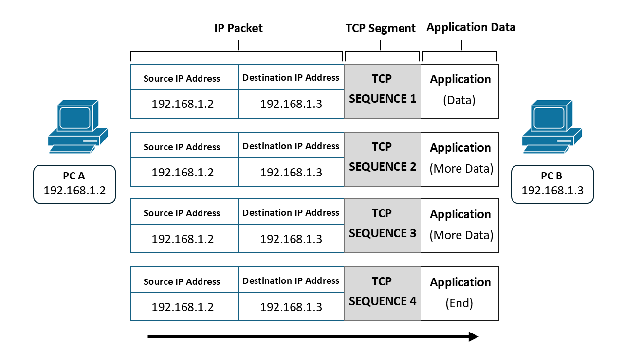
TCP segments sent from PC A to PC B
TCP Segments
 

  • Network Layer: Once the data has been broken into segments, each segment must be encapsulated (wrapped) inside an IP (Internet Protocol) packet.

    • The IP packet contains the segment from the Transport layer.
    • It also includes addressing information:
      • Source: who is sending the packet
      • Destination: who should receive the packet

    Every device that communicates on a TCP/IP-based network must have an IP address.

    • This address is how endpoints identify each other when exchanging messages (IP packets) at the Network layer. Because of that, without an IP address, communication on a TCP/IP-based network isn’t possible.

      IP addresses are logical addresses configured in the operating system. They can be assigned:

      • Manually (static IP addresses)
      • Automatically using DHCP (Dynamic Host Configuration Protocol)

      IP addresses can be changed whenever an administrator or user decides it’s necessary.

    • In this example, PC A has an IP address of 192.168.1.2 (the source IP), and PC B has an IP address of 192.168.1.3 (the destination IP). You’ll also hear these called the endpoints’ Layer 3 addresses, because IP addressing is used at Layer 3 (the Network layer).

    • Here’s a useful analogy:

      • Think of the XYZ App’s data as a letter you want to mail out.
      • The TCP segments are the individual pages of that letter.
      • TCP (and UDP) handle tasks like sequencing those pages (for example, numbering pages 1-4).
      • The IP packet is like an envelope that carries one page.

In networking, each “page” (segment) goes into its own “envelope” (IP packet). Each envelope includes a “From” address (source IP) and a “To” address (destination IP).

  • Data Link Layer: After the application data has been encapsulated into an IP packet at Layer 3, it must be passed down to Layer 2, the Data Link layer. This layer handles delivery across a local link using the device’s network adapter.

    Devices typically connect using:

    • A wired network adapter (a physical port where you plug in an Ethernet cable to a switch or router)

    • A wireless network adapter (radio communication to a wireless access point or wireless router)

    • Sometimes both

    • Network adapters use a different kind of addressing than IP. They use MAC (Media Access Control) addresses.

      • MAC addresses are tied to the network adapter hardware.
      • Unlike IP addresses, MAC addresses are considered physical and are generally persistent.

      When you assign an IP address to an endpoint, you’re ultimately assigning it to a specific physical network adapter (wired or wireless). That IP address becomes associated with that adapter’s MAC address.

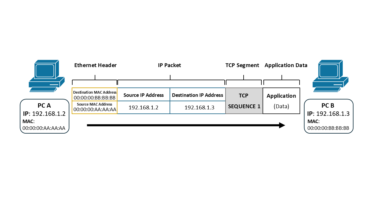
      At Layer 2, MAC addresses are placed into a structure called a frame:

      • Source MAC address (PC A’s adapter)
      • Destination MAC address (PC B’s adapter)
TCP segment encapsulated inside an IP packet and Ethernet frame
TCP Segment encapsulated within an IP packet that is encapsulated in an Ethernet Frame
  • Another layer of encapsulation happens here: the IP packet is encapsulated into a frame.

    Continuing the mailing analogy:

    • The IP packet is the envelope holding the page.
    • The Layer 2 frame is like putting that envelope inside a larger mailing envelope.

    The most common Layer 2 technology used today is Ethernet, defined by the IEEE 802.3 standard.

    • IEEE stands for the Institute of Electrical and Electronics Engineers.

    • IEEE publishes and maintains technical standards for networking protocols.

    • 802.3 is the IEEE standard for wired Layer 2 networks (Ethernet).

      For wireless networks, the IEEE 802.11 standard is used, which we call Wi‑Fi. Wi‑Fi frames also use MAC addresses to identify the wireless adapters exchanging frames.

  • Physical Layer: The Physical layer is where data actually leaves the device. Up to this point, PC A has been preparing the data by encapsulating it at each layer, but nothing has physically traveled yet.

    This layer deals with how the bits are represented and transmitted.

    • The network adapter encodes the frame into binary (1s and 0s).
    • Those bits are then transmitted over a physical medium.

    Common physical media include:

    • Wired Ethernet (copper): There are multiple cable types and standards. Today, the most common is Cat 6 (Category 6) Ethernet cabling, which uses twisted pairs of copper wires inside an outer jacket.

    • Fiber optic (also used with Ethernet): Fiber optic cables use a fiberglass core and transmit data using light signals rather than electrical signals.

    • Wireless: The binary data representing the frames is transmitted through the air using radio waves.

Now you have the full picture of what PC A does to send data to PC B. When PC B receives the data on its network adapter, it processes the frame, confirms it’s intended for PC B, and then works upward through the layers to reach the application data.

So the sender moves down the TCP/IP layers to transmit, and the receiver moves up the layers to interpret. If PC B sends data back to PC A, the same process happens in the opposite direction.

To sum up the Layers of the TCP/IP model and how it all works (from the top down):

Application Layer: Although this layer is the 5th Layer of the TCP/IP model, we still refer to it with the layer numbering scheme from the OSI model, which is “Layer 7”. This Layer generates and processes data from applications.

Transport Layer: This layer uses either TCP or UDP to break the data up into manageable “segments”, also referred to as “datagrams”

Network Layer: This layer encapsulates the segments (or “datagrams”) into IP packets and endpoints use the IP Addresses from this layer to identify each other when sending/receiving packets. It’s important to note that Routers typically operate at this layer.

Data Link Layer: This layer encapsulates the IP Packets into Frames that are exchanged between devices that share a local link. The MAC Addresses within the Frames are used to identify the physical network adapters that belong to a particular device on the link. It is important to note that Switches and Wireless Access Points typically operate at this layer.

Physical Layer: This layer is responsible for carrying the physical representation of the data, either via electrical signals on a copper wire, light signals on a fiber optic cable, or radio waves over the air from a wireless adapter.

Remember, when troubleshooting network issues as a Network Engineer, you typically want to start at the bottom layer of the TCP/IP model (which is the Physical Layer) and work your way up each layer until you get to the top (Application Layer). Network Engineers also typically focus more on Layers 1 - 3.

TCP/IP model overview

  • Based on OSI model; organizes networking into layers
  • TCP/IP model has 5 layers (vs. OSI’s 7)
  • Each layer depends on the services of the layer below

Application layer

  • Generates and processes data from applications
  • Prepares data for transmission (Layer 7 in OSI terminology)
  • Example: app breaks file into smaller pieces for sending

Transport layer

  • Uses TCP or UDP to split data into segments (TCP) or datagrams (UDP)
  • Manages data flow, sequencing, and reliability
  • Segments passed to Network layer for further encapsulation

Network layer

  • Encapsulates segments/datagrams into IP packets
  • Adds source and destination IP addresses (logical Layer 3 addresses)
  • Routers operate at this layer; enables communication between networks

Data link layer

  • Encapsulates IP packets into frames for local delivery
  • Uses MAC addresses (physical addresses) to identify network adapters
  • Switches and wireless access points operate at this layer
  • Ethernet (IEEE 802.3) and Wi-Fi (IEEE 802.11) are common standards

Physical layer

  • Transmits raw bits over physical media (copper, fiber optic, wireless)
  • Responsible for encoding and actual data transmission
  • Common media: Cat 6 Ethernet cables, fiber optics, radio waves

Troubleshooting approach

  • Start at the Physical Layer (bottom) and work upward
  • Network engineers focus mainly on Layers 1-3 (Physical, Data Link, Network)

Sign up for free to take 10 quiz questions on this topic

Previous
Next  | 1.5.1 The Transport Layer
All rights reserved ©2016 - 2026 Achievable, Inc.

The layers of the TCP/IP model

As you saw on the first page of this book (Chapter 1.1 What is networking?), the networks we use today are based on the TCP/IP model. To understand how one computer exchanges data with another, you first need a clear picture of what the TCP/IP model is and what each layer does.

TCP/IP model

The TCP/IP model is based on an older networking framework called the OSI (Open Systems Interconnection) model. Both models organize networking technologies and protocols into layers that work together to deliver data from one endpoint to another.

  • The OSI model has seven layers.
  • The TCP/IP model is a more modern, condensed version with five layers.

You’ll also see people casually refer to the TCP/IP model as the “OSI model.” What they usually mean is that the TCP/IP model maps closely to OSI concepts and is commonly used in real-world networking.

A helpful way to think about layers is to compare them to building a house. Different specialists handle different parts of the job:

  • One team lays the foundation.
  • Another builds the frame.
  • Others install plumbing and electrical.

Each step depends on the earlier steps. You can’t install windows without walls, and you can’t finish a kitchen without plumbing. Networking layers work the same way: each layer relies on the services of the layer below it.

A concrete example makes this easier to see.

Say PC A wants to send a file to PC B. We’ll walk through what happens at each layer of the TCP/IP model.

When troubleshooting, you typically start at the bottom (Physical) and work upward. For learning how data is created and prepared to be sent, it’s clearer to start at the top (Application) and work downward.

  • Application Layer: PC A is running an application called the “XYZ App.” It wants to send a file to PC B, which is running the same app and will process the file. The XYZ App prepares the file for transmission, often by breaking it into smaller pieces that can be sent efficiently. Because this is a TCP-based application, it hands the data to TCP on the computer.

  • Transport Layer: This layer uses either TCP or UDP to split the data into smaller, manageable pieces.

    • With TCP, these pieces are called segments.
    • With UDP, these pieces are often called datagrams.

    Breaking data into smaller units helps avoid sending one long continuous stream that could create bottlenecks. In this example, we’re using TCP.


  • Network Layer: Once the data has been broken into segments, each segment must be encapsulated (wrapped) inside an IP (Internet Protocol) packet.

    • The IP packet contains the segment from the Transport layer.
    • It also includes addressing information:
      • Source: who is sending the packet
      • Destination: who should receive the packet

    Every device that communicates on a TCP/IP-based network must have an IP address.

    • This address is how endpoints identify each other when exchanging messages (IP packets) at the Network layer. Because of that, without an IP address, communication on a TCP/IP-based network isn’t possible.

      IP addresses are logical addresses configured in the operating system. They can be assigned:

      • Manually (static IP addresses)
      • Automatically using DHCP (Dynamic Host Configuration Protocol)

      IP addresses can be changed whenever an administrator or user decides it’s necessary.

    • In this example, PC A has an IP address of 192.168.1.2 (the source IP), and PC B has an IP address of 192.168.1.3 (the destination IP). You’ll also hear these called the endpoints’ Layer 3 addresses, because IP addressing is used at Layer 3 (the Network layer).

    • Here’s a useful analogy:

      • Think of the XYZ App’s data as a letter you want to mail out.
      • The TCP segments are the individual pages of that letter.
      • TCP (and UDP) handle tasks like sequencing those pages (for example, numbering pages 1-4).
      • The IP packet is like an envelope that carries one page.

In networking, each “page” (segment) goes into its own “envelope” (IP packet). Each envelope includes a “From” address (source IP) and a “To” address (destination IP).

  • Data Link Layer: After the application data has been encapsulated into an IP packet at Layer 3, it must be passed down to Layer 2, the Data Link layer. This layer handles delivery across a local link using the device’s network adapter.

    Devices typically connect using:

    • A wired network adapter (a physical port where you plug in an Ethernet cable to a switch or router)

    • A wireless network adapter (radio communication to a wireless access point or wireless router)

    • Sometimes both

    • Network adapters use a different kind of addressing than IP. They use MAC (Media Access Control) addresses.

      • MAC addresses are tied to the network adapter hardware.
      • Unlike IP addresses, MAC addresses are considered physical and are generally persistent.

      When you assign an IP address to an endpoint, you’re ultimately assigning it to a specific physical network adapter (wired or wireless). That IP address becomes associated with that adapter’s MAC address.

      At Layer 2, MAC addresses are placed into a structure called a frame:

      • Source MAC address (PC A’s adapter)
      • Destination MAC address (PC B’s adapter)
  • Another layer of encapsulation happens here: the IP packet is encapsulated into a frame.

    Continuing the mailing analogy:

    • The IP packet is the envelope holding the page.
    • The Layer 2 frame is like putting that envelope inside a larger mailing envelope.

    The most common Layer 2 technology used today is Ethernet, defined by the IEEE 802.3 standard.

    • IEEE stands for the Institute of Electrical and Electronics Engineers.

    • IEEE publishes and maintains technical standards for networking protocols.

    • 802.3 is the IEEE standard for wired Layer 2 networks (Ethernet).

      For wireless networks, the IEEE 802.11 standard is used, which we call Wi‑Fi. Wi‑Fi frames also use MAC addresses to identify the wireless adapters exchanging frames.

  • Physical Layer: The Physical layer is where data actually leaves the device. Up to this point, PC A has been preparing the data by encapsulating it at each layer, but nothing has physically traveled yet.

    This layer deals with how the bits are represented and transmitted.

    • The network adapter encodes the frame into binary (1s and 0s).
    • Those bits are then transmitted over a physical medium.

    Common physical media include:

    • Wired Ethernet (copper): There are multiple cable types and standards. Today, the most common is Cat 6 (Category 6) Ethernet cabling, which uses twisted pairs of copper wires inside an outer jacket.

    • Fiber optic (also used with Ethernet): Fiber optic cables use a fiberglass core and transmit data using light signals rather than electrical signals.

    • Wireless: The binary data representing the frames is transmitted through the air using radio waves.

Now you have the full picture of what PC A does to send data to PC B. When PC B receives the data on its network adapter, it processes the frame, confirms it’s intended for PC B, and then works upward through the layers to reach the application data.

So the sender moves down the TCP/IP layers to transmit, and the receiver moves up the layers to interpret. If PC B sends data back to PC A, the same process happens in the opposite direction.

To sum up the Layers of the TCP/IP model and how it all works (from the top down):

Application Layer: Although this layer is the 5th Layer of the TCP/IP model, we still refer to it with the layer numbering scheme from the OSI model, which is “Layer 7”. This Layer generates and processes data from applications.

Transport Layer: This layer uses either TCP or UDP to break the data up into manageable “segments”, also referred to as “datagrams”

Network Layer: This layer encapsulates the segments (or “datagrams”) into IP packets and endpoints use the IP Addresses from this layer to identify each other when sending/receiving packets. It’s important to note that Routers typically operate at this layer.

Data Link Layer: This layer encapsulates the IP Packets into Frames that are exchanged between devices that share a local link. The MAC Addresses within the Frames are used to identify the physical network adapters that belong to a particular device on the link. It is important to note that Switches and Wireless Access Points typically operate at this layer.

Physical Layer: This layer is responsible for carrying the physical representation of the data, either via electrical signals on a copper wire, light signals on a fiber optic cable, or radio waves over the air from a wireless adapter.

Remember, when troubleshooting network issues as a Network Engineer, you typically want to start at the bottom layer of the TCP/IP model (which is the Physical Layer) and work your way up each layer until you get to the top (Application Layer). Network Engineers also typically focus more on Layers 1 - 3.

Key points

TCP/IP model overview

  • Based on OSI model; organizes networking into layers
  • TCP/IP model has 5 layers (vs. OSI’s 7)
  • Each layer depends on the services of the layer below

Application layer

  • Generates and processes data from applications
  • Prepares data for transmission (Layer 7 in OSI terminology)
  • Example: app breaks file into smaller pieces for sending

Transport layer

  • Uses TCP or UDP to split data into segments (TCP) or datagrams (UDP)
  • Manages data flow, sequencing, and reliability
  • Segments passed to Network layer for further encapsulation

Network layer

  • Encapsulates segments/datagrams into IP packets
  • Adds source and destination IP addresses (logical Layer 3 addresses)
  • Routers operate at this layer; enables communication between networks

Data link layer

  • Encapsulates IP packets into frames for local delivery
  • Uses MAC addresses (physical addresses) to identify network adapters
  • Switches and wireless access points operate at this layer
  • Ethernet (IEEE 802.3) and Wi-Fi (IEEE 802.11) are common standards

Physical layer

  • Transmits raw bits over physical media (copper, fiber optic, wireless)
  • Responsible for encoding and actual data transmission
  • Common media: Cat 6 Ethernet cables, fiber optics, radio waves

Troubleshooting approach

  • Start at the Physical Layer (bottom) and work upward
  • Network engineers focus mainly on Layers 1-3 (Physical, Data Link, Network)

More from Introduction to networking

  • What is networking?
  • Components of a TCP/IP based network
  • How devices communicate on a TCP/IP based network