



Weight and volume relationships
This chapter covers the following:
- Weight and volume relationships
- Soil compaction and classification parameters
- Permeability and seepage
Weight and volume relationships
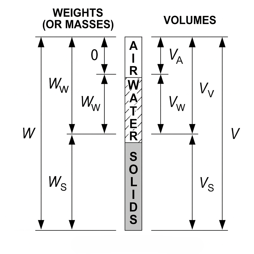
In soil mechanics, weight-volume relationships help you describe and predict soil behavior. They’re based on the three-phase system, which treats soil as a mixture of:
- solids
- water
- air
Three-phase system
We’ll use the following symbols:
- = total volume
- = volume of solids
- = volume of water
- = volume of air
- = total weight
- = weight of solids
- = weight of water
The total volume is the sum of the three phase volumes:
The volume of voids is the part of the soil volume not occupied by solids (so it includes both air and water):
Index properties
These properties describe the composition of a soil sample in terms of its solid, water, and air phases.
Water content
Water content is the ratio of water weight to solids weight:
Total (bulk) unit weight
Total (bulk) unit weight is total weight per total volume:
Dry unit weight
Dry unit weight uses only the weight of solids (but still divides by the total volume):
Saturated unit weight
Saturated unit weight applies when the voids are completely filled with water (no air):
Void ratio
Void ratio compares void volume to solids volume:
Porosity
Porosity is the fraction of the total volume that is void space:
Degree of saturation
Degree of saturation is the fraction of the void space that is filled with water:
Specific gravity of solids
Specific gravity of solids compares the density of soil solids to the density of water:
Quick conversion formula
These relationships are commonly used to convert between properties:
Example: Phase relationships
This problem gives the total volume, solids weight, water content, and specific gravity of a soil sample. It asks for the bulk unit weight, dry unit weight, volume of voids, and porosity.
Given:
Find: bulk unit weight, dry unit weight, volume of voids, and porosity (steps 3, 4, 6, and 7 below; steps 1, 2, and 5 find the intermediate values).
1. Weight of water:
Convert the water content to a decimal and multiply by the solids weight.
2. Total weight:
Add the solids and water weights.
3. Bulk unit weight:
Divide total weight by total volume.
4. Dry unit weight:
Divide solids weight by total volume.
Next, find the volume of solids using the specific gravity and unit weight of water. Subtract that from the total volume to get the volume of voids. Then divide by the total volume to find the porosity, about forty nine point seven percent.
5. Volume of solids:
Use the relationship between solids weight, specific gravity, and the unit weight of water. Carry at least 4-5 significant figures here rather than rounding early - answer choices in this kind of problem are often closely spaced, and an early rounding shifts the final porosity enough to pick the wrong option.
Assume :
6. Volume of voids:
Subtract the solids volume from the total volume.
7. Porosity:
Compute void volume as a fraction of total volume.
Answer: , , ,
Soil compaction and classification parameters
Relative density
Relative density compares the in-place void ratio (or dry unit weight) of a granular soil to its loosest and densest possible states. Use the void-ratio form when and are known from lab testing; use the dry-unit-weight form when only field and lab unit-weight data are available - the two forms are equivalent.
or
Relative compaction (%)
Relative compaction compares the field dry unit weight to the maximum dry unit weight from a compaction test.
Plasticity index
Plasticity index is the range of water contents over which a fine-grained soil behaves plastically.
- = liquid limit
- = plastic limit
Coefficient of uniformity
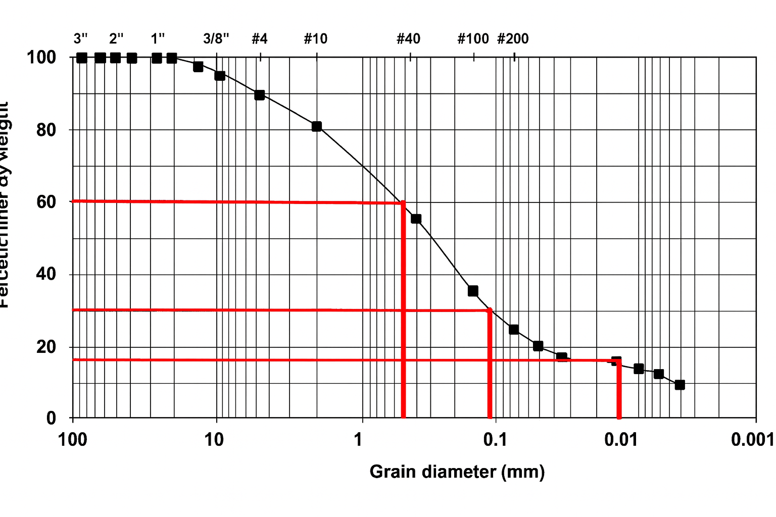
The coefficient of uniformity describes how spread out the particle sizes are.
Coefficient of concavity (or curvature)
The coefficient of concavity (curvature) describes the shape of the gradation curve.
Under the USCS, a well-graded gravel needs and ; a well-graded sand needs and . A soil that fails either test is classified as poorly-graded.
Example: Gradation parameters
This problem gives the liquid limit, plastic limit, and three particle diameters for a sand-size soil. It asks for the plasticity index, the coefficient of uniformity, the coefficient of concavity, and whether the gradation is well graded.
Given: a sand-size soil with , , , ,
Find: , , , and whether the gradation is well-graded
Since and , this sand meets both well-graded criteria.
Answer: , , , well-graded
Permeability and seepage
Hydraulic conductivity (coefficient of permeability)
Hydraulic conductivity measures how easily water flows through soil.
Constant head test:
where,
Falling head test:
Where:
- = cross-sectional area of test specimen perpendicular to flow
- = cross-sectional area of reservoir tube
- = elapsed time
- = head at time
- = head at time
- = length of soil column
Discharge velocity and seepage velocity
where, and
Flow nets
A flow net is a combination of flow lines and equipotential lines.
- A flow line is a line along which a water particle travels.
- An equipotential line connects points of equal total head.
Key properties used when constructing and interpreting a flow net:
- There is no flow along equipotential lines, which are perpendicular to flow lines.
- The total head along an equipotential line is equal at all points.
- Flow lines cannot cross other flow lines and equipotential lines cannot cross other equipotential lines.
- Equipotential lines intersect the flow lines at right angles.
- Each element of a flow net must be a curvilinear square (sides may be curved, but a circle must be inscribed within it that touches all four sides).
The total flow rate through a flow net is found by:
Where:
- = total flow rate
- = number of flow channels in a flow net
- = number of potential drops
- = head change from upstream to downstream
- = coefficient of permeability
- = length of structure (i.e., bank-to-bank)
- Without , gives the flow rate per unit width of the structure; multiplying by (the out-of-plane width) scales this up to the total flow rate .
Example: Flow net discharge
Given:
- flow channels
- potential drops
- (out-of-plane width)
Find: total flow rate
Substitute the given values into the flow-net equation.
Answer:
Factor of safety against seepage liquefaction
where,