


Achievable logoAchievable logo
FE Civil
Sign in
Sign up
Purchase
Textbook
Practice exams
Support
How it works
Exam catalog
Mountain with a flag at the peak
Textbook
Introduction
1. Mathematics
2. Combinatorics, probability and statistics
3. Engineering economics
4. Statics
5. Materials
6. Dynamics
7. Mechanics of materials
8. Fluid mechanics
9. Soil mechanics
10. Structural engineering
11. Concrete structure design
12. Water resources engineering
13. Environmental engineering
14. Transportation engineering
15. Surveying, construction, ethics and professional practice
16. Wrapping up
(change me)
Achievable logoAchievable logo
11. Concrete structure design
Achievable FE Civil
Our FE Civil course is currently in development and is a work-in-progress.

Concrete structure design

9 min read
Font
Discuss
Share
Feedback

This chapter covers the following:

  • Beam design
  • Slab design
  • Column design
  • Footing design

Beam design

Beam design focuses on analyzing and proportioning reinforced concrete members subjected mainly to bending and shear. You’ll use strain compatibility, internal force equilibrium, and strength reduction concepts to determine the required flexural reinforcement.

This section covers:

  • Singly and doubly reinforced beams
  • Rectangular and T-beam sections
  • Strength, ductility, and serviceability requirements consistent with reinforced concrete design principles
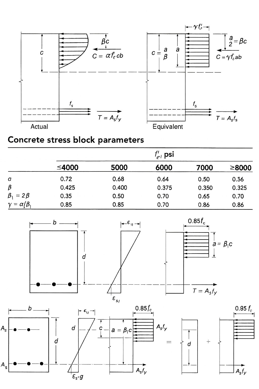
A diagram explaining the concrete compression stress block and strain distribution used in reinforced concrete beam design analysis.
Concrete beam design

Mu​=moment of moment diagram

z=lever arm=larger of⎩⎨⎧​0.9⋅dd−2a​​

As​=ϕfy​zMu​​

Ac​=0.85fc′​As​fy​​

If Ac​<Af​, the neutral axis (N.A.) is in the flange, so treat the section as a rectangular beam.

Rn​=ϕbd2Mu​​

ρ=0.85⋅fy​fc′​​(1−1−0.85fc′​2⋅Rn​​​)

ρmax​=0.85⋅β⋅fy​fc′​​⋅ϵcu​+ϵt​ϵcu​​

If ρ<ρmax​, the beam is singly reinforced. Then:

ρmin​=larger of⎩⎨⎧​fy​3fc′​​​fy​200​​

ρmin​<ρ<ρmax​

As​=ρbd

a=0.85fc′​bAs​fy​​

c=β1​a​

ϵt​=c(d−c)​,ϵt​>0.005

Therefore ϕ is OK, or calculate ϕ:

ϕMn​=ϕAs​fy​(d−2a​)>Mu​

But if ρ>ρmax​, the beam is doubly reinforced. Then:

As​=As′​+ρmax​bd

As′​=(ρ−ρmax​)bd

As​fy​=0.85fc′​b1​c+As′​(cc−d′​)⋅ϵs​Es​

Solve for c and compute a=β1​c.

Therefore ϕ is OK, or calculate ϕ.

fs′​=(As​−As′​As′​​)fy​

ϕMn​=ϕ[As​fy​(d−2a​)+As′​fs′​(d−d′)]>Mu​

If Ac​>Af​, the neutral axis (N.A.) is below the flange, so treat the section as a T-beam.

beff​=smaller of⎩⎨⎧​L/4bw​+16t(beam spacing)​

y=Af​⋅(2t​)+(Ac​−Af​)⋅(Ac​t+2bw​(Ac​−Af​)​​)

z=lever arm=d−yˉ​

As​=ϕfy​zMu​​

a=t+bw​(Ac​−Af​)​,0.85fc′​beff​As​fy​​

c=β1​a​

ϵt​=c(d−c)​,ϵt​>0.005

Therefore ϕ is OK, or calculate ϕ.

ϕMn​=ϕ0.85fc′​[t(beff​−bw​)(d−2t​)+abw​(d−2a​)]>Mu​

Shear design

ϕVn​≥Vu​

Nominal shear strength:

Vn​=Vc​+Vs​

Vc​=2λfc′​​bw​d

Where:

  • λ=1.0 for normal weight concrete (NWC)
  • λ=0.75 for lightweight concrete

Vs​=sAv​fy​d​(may not exceed 8bw​d/fc′​​)

Required and maximum-permitted stirrup spacing s

  • If:

    Vu​≤2ϕVc​​⇒No stirrups required

  • If:

    Vu​>2ϕVc​​⇒Use the following table (Av​ given)

Please see Stirrup spacing table from FE Handbook.

Slab design

Slab design involves selecting slab thickness and reinforcement to resist flexural moments and control cracking under dead and live loads. This section covers minimum thickness requirements, self-weight calculations, and flexural reinforcement design using strength-based methods. It also includes temperature and shrinkage reinforcement for durability and long-term performance.

Select minimum slab thickness according to guidelines (t)

Calculate self weight from slab thickness t.

self wt=(12t​)⋅150

Calculate moment from dead load and live load combination:

ρmax​=0.85⋅β⋅fy​fc′​​⋅ϵu​+ϵt​ϵu​​

Consider ρ=ρmax​ to calculate d:

dreq​=ϕρfy​b(1−0.59fc′​ρfy​​)Mmax​​​

Adjust d:

If dpro​>dreq​

Rn​=ϕbd2Mu​​

ρ=0.85⋅fy​fc′​​(1−1−0.85fc′​2⋅Rn​​​)

As​=ρbd

Check:

As​>As,min​

Select temperature and shrinkage steel

Column design

Column design addresses the strength and stability of reinforced concrete members subjected to axial load, with or without bending. This section covers axial load capacity, longitudinal reinforcement limits, and confinement requirements using ties or spirals. Interaction relationships and strength reduction factors are used to verify adequacy, with attention to reinforcement detailing and spacing requirements.

ϕPn​=αϕ[0.85fc′​(Ag​−Ast​)+fy​Ast​]

Use:

Ast​=s⋅Ag​;s=(0.01∼0.08)

If longitudinal bar #10 or smaller, then use tie #3.

Else use tie #4.

Spacing of tie bar = smallest of:

  • 48×tie bar dia
  • 16×longitudinal bar dia
  • least dimension

Select arrangement as below so that clear spacing between longitudinal bars >1" or dia of tie bar.

Rn​=ϕfc′​Ag​hMn​​

ϕPnx​=ϕKnx​fc′​Ag​

ϕPno​=αϕ[0.85fc′​(1−s)+sfy​]Ag​

ϕPn​1​=ϕPnx​1​+ϕPny​1​−ϕPno​1​

ϕPn​>Pu​so OK

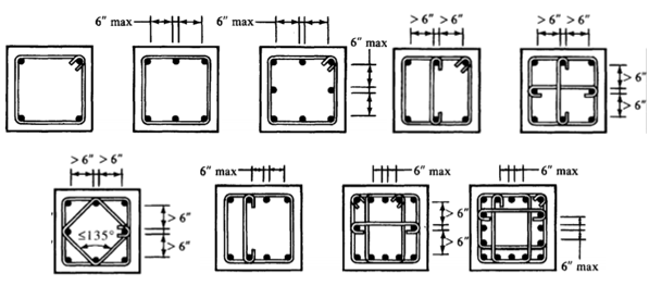
A set of reinforced concrete column detailing diagrams showing proper lateral tie and hoop configurations with spacing limits for confinement.
Concrete lateral ties for column

Footing design

Footing design focuses on transferring loads from columns or walls to supporting soil without exceeding allowable bearing pressures. This section covers required footing area, factored soil pressures, and effective depth selection. Flexural, one-way shear, and punching shear checks are used to confirm adequate strength and structural integrity for isolated and combined footings.

A=larger of⎩⎨⎧​​BCDL+LL​1.33⋅BCDL+LL+EQL​1.33⋅BCDL+LL+WL​​

qu​=A1.2⋅DL+1.6⋅LL​

Adjust d=2A​

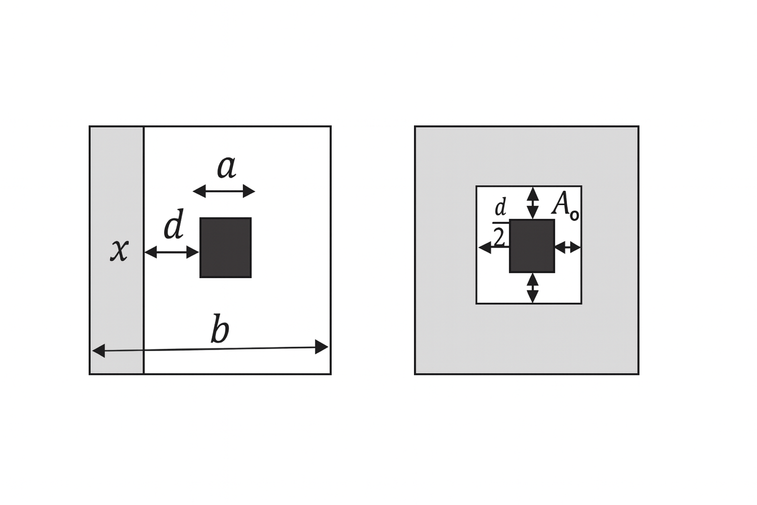
A schematic showing the geometry and critical section for punching shear around a concentrated column load on a concrete footing.
Concrete footing beam and punching shear

Check beam shear:

qu​⋅w<2λfc′​​⋅bd

Check punching shear:

qu​(A−Ao​)<4λfc′​​⋅Po​d

So, d is OK.

Mu​=81​qu​(b−a)2

Rn​=ϕbd2Mu​​

ρ=0.85⋅fy​fc′​​(1−1−0.85fc′​2⋅Rn​​​)

ρmin​=max(fy​3fc′​​​,fy​200​)

As​=max(ρmin​bd,ρbd)

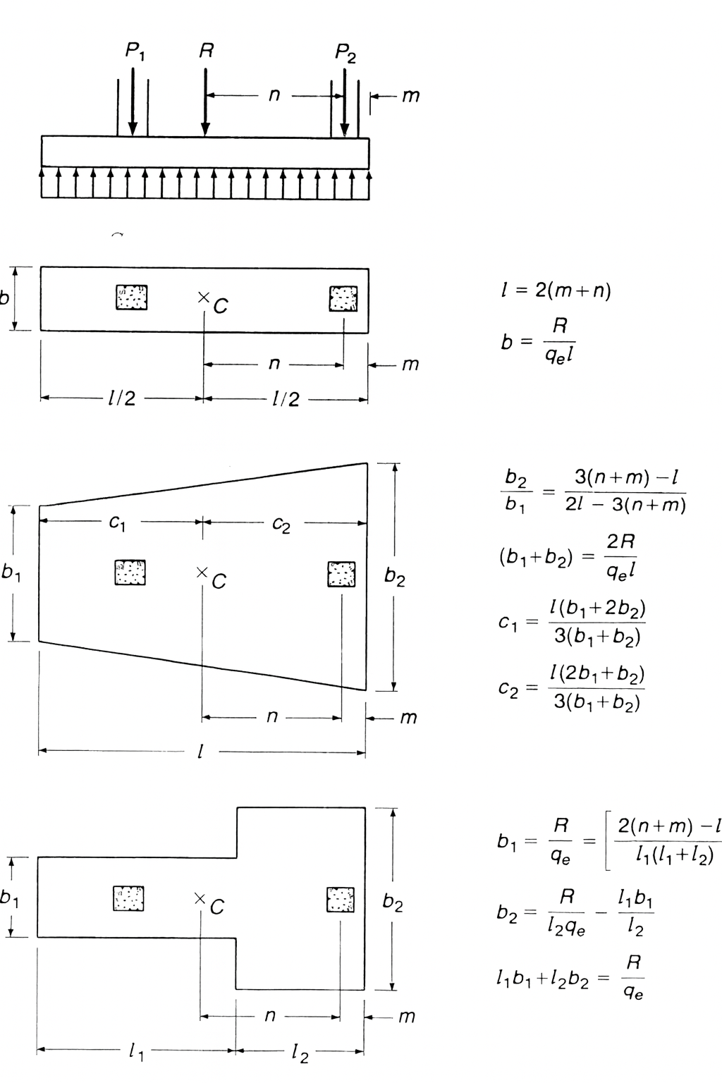
A schematic illustrating the analysis and design of a combined footing under two column loads, including resultant location, footing dimensions, and soil pressure distribution.
Concrete combined footing design

Beam design

  • Analyze for bending and shear using strain compatibility, force equilibrium, strength reduction
  • Singly vs. doubly reinforced beams:
    • ρ<ρmax​: singly reinforced; ρ>ρmax​: doubly reinforced
  • Key formulas:
    • As​=ϕfy​zMu​​, Ac​=0.85fc′​As​fy​​
    • Rn​=ϕbd2Mu​​, ρ=0.85fy​fc′​​(1−1−0.85fc′​2Rn​​​)
    • For T-beams: use beff​, check N.A. location to determine section type

Shear design

  • ϕVn​≥Vu​ for safety
  • Vn​=Vc​+Vs​:
    • Vc​=2λfc′​​bw​d
    • Vs​=sAv​fy​d​
  • Stirrup spacing based on Vu​ vs. ϕVc​/2; use FE Handbook table

Slab design

  • Select minimum thickness t per guidelines; calculate self-weight: (12t​)⋅150
  • Flexural design:
    • Use ρmax​ to size d: dreq​=ϕρfy​b(1−0.59fc′​ρfy​​)Mmax​​​
    • As​=ρbd, check As​>As,min​
  • Provide temperature and shrinkage reinforcement

Column design

  • Axial load capacity: ϕPn​=αϕ[0.85fc′​(Ag​−Ast​)+fy​Ast​]
  • Longitudinal reinforcement ratio s=0.01 to 0.08; tie size and spacing per bar size
  • Interaction equations for combined axial and bending; ϕPn​>Pu​ required

Footing design

  • Area: A=max(BCDL+LL​,1.33BCDL+LL+EQL​,1.33BCDL+LL+WL​)
  • Factored soil pressure: qu​=A1.2DL+1.6LL​
  • Check:
    • Beam shear: qu​w<2λfc′​​bd
    • Punching shear: qu​(A−Ao​)<4λfc′​​Po​d
  • Flexural reinforcement: As​=max(ρmin​bd,ρbd), with ρ from Rn​ formula

Sign up for free to take 5 quiz questions on this topic

Previous
Next  | 12.1 Open channel flow
All rights reserved ©2016 - 2026 Achievable, Inc.

Concrete structure design

This chapter covers the following:

  • Beam design
  • Slab design
  • Column design
  • Footing design

Beam design

Beam design focuses on analyzing and proportioning reinforced concrete members subjected mainly to bending and shear. You’ll use strain compatibility, internal force equilibrium, and strength reduction concepts to determine the required flexural reinforcement.

This section covers:

  • Singly and doubly reinforced beams
  • Rectangular and T-beam sections
  • Strength, ductility, and serviceability requirements consistent with reinforced concrete design principles

Mu​=moment of moment diagram

z=lever arm=larger of⎩⎨⎧​0.9⋅dd−2a​​

As​=ϕfy​zMu​​

Ac​=0.85fc′​As​fy​​

If Ac​<Af​, the neutral axis (N.A.) is in the flange, so treat the section as a rectangular beam.

Rn​=ϕbd2Mu​​

ρ=0.85⋅fy​fc′​​(1−1−0.85fc′​2⋅Rn​​​)

ρmax​=0.85⋅β⋅fy​fc′​​⋅ϵcu​+ϵt​ϵcu​​

If ρ<ρmax​, the beam is singly reinforced. Then:

ρmin​=larger of⎩⎨⎧​fy​3fc′​​​fy​200​​

ρmin​<ρ<ρmax​

As​=ρbd

a=0.85fc′​bAs​fy​​

c=β1​a​

ϵt​=c(d−c)​,ϵt​>0.005

Therefore ϕ is OK, or calculate ϕ:

ϕMn​=ϕAs​fy​(d−2a​)>Mu​

But if ρ>ρmax​, the beam is doubly reinforced. Then:

As​=As′​+ρmax​bd

As′​=(ρ−ρmax​)bd

As​fy​=0.85fc′​b1​c+As′​(cc−d′​)⋅ϵs​Es​

Solve for c and compute a=β1​c.

Therefore ϕ is OK, or calculate ϕ.

fs′​=(As​−As′​As′​​)fy​

ϕMn​=ϕ[As​fy​(d−2a​)+As′​fs′​(d−d′)]>Mu​

If Ac​>Af​, the neutral axis (N.A.) is below the flange, so treat the section as a T-beam.

beff​=smaller of⎩⎨⎧​L/4bw​+16t(beam spacing)​

y=Af​⋅(2t​)+(Ac​−Af​)⋅(Ac​t+2bw​(Ac​−Af​)​​)

z=lever arm=d−yˉ​

As​=ϕfy​zMu​​

a=t+bw​(Ac​−Af​)​,0.85fc′​beff​As​fy​​

c=β1​a​

ϵt​=c(d−c)​,ϵt​>0.005

Therefore ϕ is OK, or calculate ϕ.

ϕMn​=ϕ0.85fc′​[t(beff​−bw​)(d−2t​)+abw​(d−2a​)]>Mu​

Shear design

ϕVn​≥Vu​

Nominal shear strength:

Vn​=Vc​+Vs​

Vc​=2λfc′​​bw​d

Where:

  • λ=1.0 for normal weight concrete (NWC)
  • λ=0.75 for lightweight concrete

Vs​=sAv​fy​d​(may not exceed 8bw​d/fc′​​)

Required and maximum-permitted stirrup spacing s

  • If:

    Vu​≤2ϕVc​​⇒No stirrups required

  • If:

    Vu​>2ϕVc​​⇒Use the following table (Av​ given)

Please see Stirrup spacing table from FE Handbook.

Slab design

Slab design involves selecting slab thickness and reinforcement to resist flexural moments and control cracking under dead and live loads. This section covers minimum thickness requirements, self-weight calculations, and flexural reinforcement design using strength-based methods. It also includes temperature and shrinkage reinforcement for durability and long-term performance.

Select minimum slab thickness according to guidelines (t)

Calculate self weight from slab thickness t.

self wt=(12t​)⋅150

Calculate moment from dead load and live load combination:

ρmax​=0.85⋅β⋅fy​fc′​​⋅ϵu​+ϵt​ϵu​​

Consider ρ=ρmax​ to calculate d:

dreq​=ϕρfy​b(1−0.59fc′​ρfy​​)Mmax​​​

Adjust d:

If dpro​>dreq​

Rn​=ϕbd2Mu​​

ρ=0.85⋅fy​fc′​​(1−1−0.85fc′​2⋅Rn​​​)

As​=ρbd

Check:

As​>As,min​

Select temperature and shrinkage steel

Column design

Column design addresses the strength and stability of reinforced concrete members subjected to axial load, with or without bending. This section covers axial load capacity, longitudinal reinforcement limits, and confinement requirements using ties or spirals. Interaction relationships and strength reduction factors are used to verify adequacy, with attention to reinforcement detailing and spacing requirements.

ϕPn​=αϕ[0.85fc′​(Ag​−Ast​)+fy​Ast​]

Use:

Ast​=s⋅Ag​;s=(0.01∼0.08)

If longitudinal bar #10 or smaller, then use tie #3.

Else use tie #4.

Spacing of tie bar = smallest of:

  • 48×tie bar dia
  • 16×longitudinal bar dia
  • least dimension

Select arrangement as below so that clear spacing between longitudinal bars >1" or dia of tie bar.

Rn​=ϕfc′​Ag​hMn​​

ϕPnx​=ϕKnx​fc′​Ag​

ϕPno​=αϕ[0.85fc′​(1−s)+sfy​]Ag​

ϕPn​1​=ϕPnx​1​+ϕPny​1​−ϕPno​1​

ϕPn​>Pu​so OK

Footing design

Footing design focuses on transferring loads from columns or walls to supporting soil without exceeding allowable bearing pressures. This section covers required footing area, factored soil pressures, and effective depth selection. Flexural, one-way shear, and punching shear checks are used to confirm adequate strength and structural integrity for isolated and combined footings.

A=larger of⎩⎨⎧​​BCDL+LL​1.33⋅BCDL+LL+EQL​1.33⋅BCDL+LL+WL​​

qu​=A1.2⋅DL+1.6⋅LL​

Adjust d=2A​

Check beam shear:

qu​⋅w<2λfc′​​⋅bd

Check punching shear:

qu​(A−Ao​)<4λfc′​​⋅Po​d

So, d is OK.

Mu​=81​qu​(b−a)2

Rn​=ϕbd2Mu​​

ρ=0.85⋅fy​fc′​​(1−1−0.85fc′​2⋅Rn​​​)

ρmin​=max(fy​3fc′​​​,fy​200​)

As​=max(ρmin​bd,ρbd)

Key points

Beam design

  • Analyze for bending and shear using strain compatibility, force equilibrium, strength reduction
  • Singly vs. doubly reinforced beams:
    • ρ<ρmax​: singly reinforced; ρ>ρmax​: doubly reinforced
  • Key formulas:
    • As​=ϕfy​zMu​​, Ac​=0.85fc′​As​fy​​
    • Rn​=ϕbd2Mu​​, ρ=0.85fy​fc′​​(1−1−0.85fc′​2Rn​​​)
    • For T-beams: use beff​, check N.A. location to determine section type

Shear design

  • ϕVn​≥Vu​ for safety
  • Vn​=Vc​+Vs​:
    • Vc​=2λfc′​​bw​d
    • Vs​=sAv​fy​d​
  • Stirrup spacing based on Vu​ vs. ϕVc​/2; use FE Handbook table

Slab design

  • Select minimum thickness t per guidelines; calculate self-weight: (12t​)⋅150
  • Flexural design:
    • Use ρmax​ to size d: dreq​=ϕρfy​b(1−0.59fc′​ρfy​​)Mmax​​​
    • As​=ρbd, check As​>As,min​
  • Provide temperature and shrinkage reinforcement

Column design

  • Axial load capacity: ϕPn​=αϕ[0.85fc′​(Ag​−Ast​)+fy​Ast​]
  • Longitudinal reinforcement ratio s=0.01 to 0.08; tie size and spacing per bar size
  • Interaction equations for combined axial and bending; ϕPn​>Pu​ required

Footing design

  • Area: A=max(BCDL+LL​,1.33BCDL+LL+EQL​,1.33BCDL+LL+WL​)
  • Factored soil pressure: qu​=A1.2DL+1.6LL​
  • Check:
    • Beam shear: qu​w<2λfc′​​bd
    • Punching shear: qu​(A−Ao​)<4λfc′​​Po​d
  • Flexural reinforcement: As​=max(ρmin​bd,ρbd), with ρ from Rn​ formula

Related readings

  • Introduction
  • Engineering economics
  • Statics
  • Dynamics
  • Mechanics of materials