



Circuits
Circuit Diagram
Reading a circuit diagram is crucial for electronics. Let’s start with the basics.
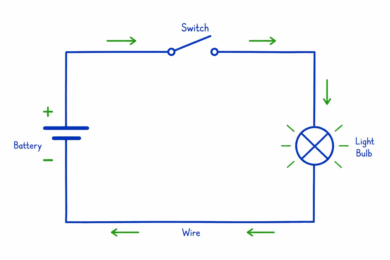
Here we can see the battery, a switch, a light bulb, and the wire connecting everything. The arrows show the direction current would flow if the switch were closed — from the positive end of the battery, through the switch, to the light bulb, and back. Right now, though, the switch is drawn open, so the loop is broken and no current is actually flowing. We’ll talk more about open and closed switches in a moment.
Charge is the electrical property carried by the particles in a circuit. Current is the rate at which that charge flows through a wire.
Load is what consumes the electricity. This could be a lamp, a motor, a TV, or a heater.
Open vs. closed circuits
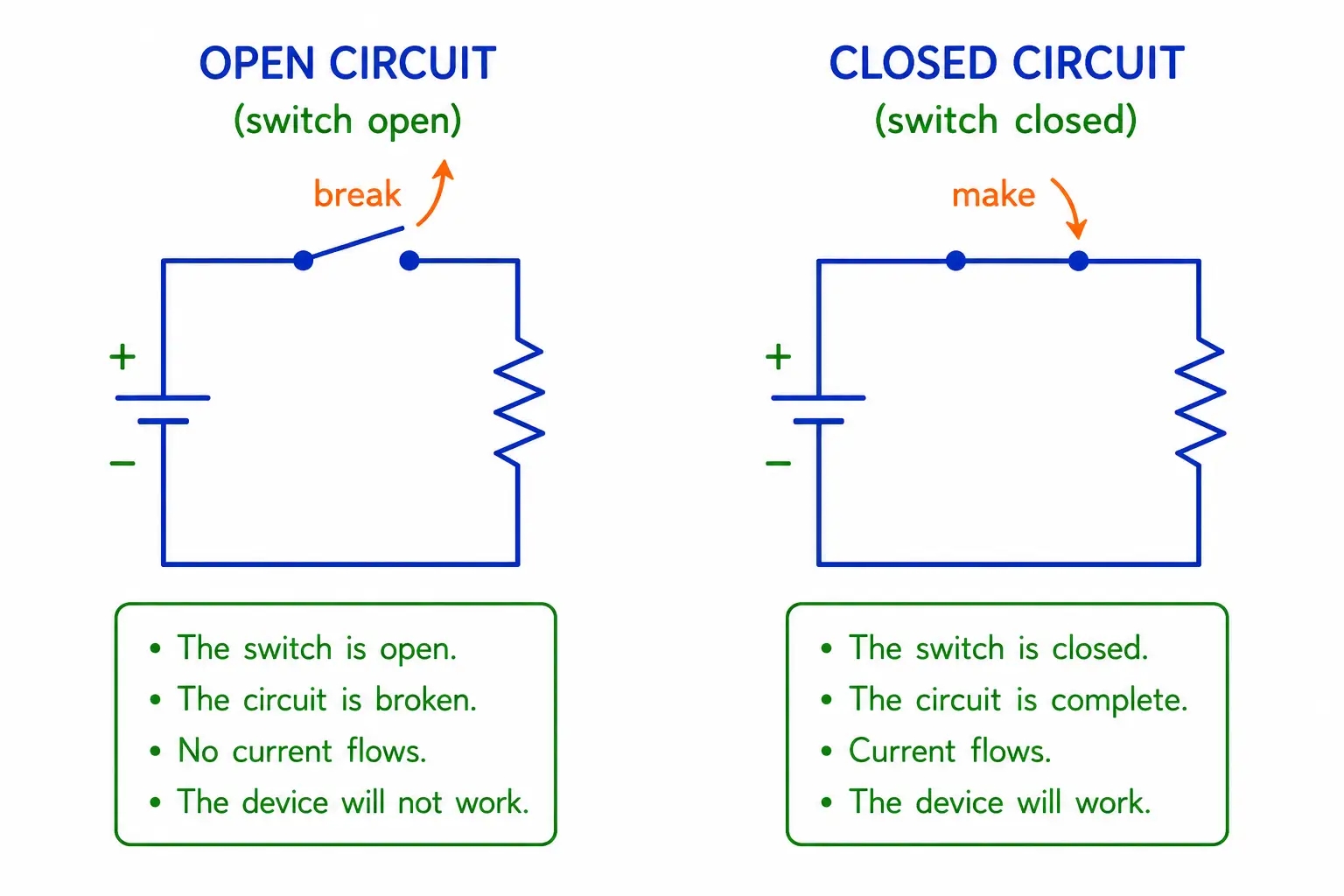
For electrical charge to flow through a circuit, the circuit must form a closed loop. If the loop is ever broken, the current will stop flowing.
An open circuit is not a closed loop, so electric current cannot flow through it.
A closed circuit is a complete loop through which electric current can flow.
To easily open or close a circuit, we often use a switch. When a switch is flipped to the “on” position, it will close the circuit, allowing electrical current to flow and turning the device on.
When a switch is flipped to the “off” position, it opens the circuit, stopping electrical current from flowing and turning the device off.
Types of Circuits
The two ways of wiring a circuit are series and parallel.
Series circuits
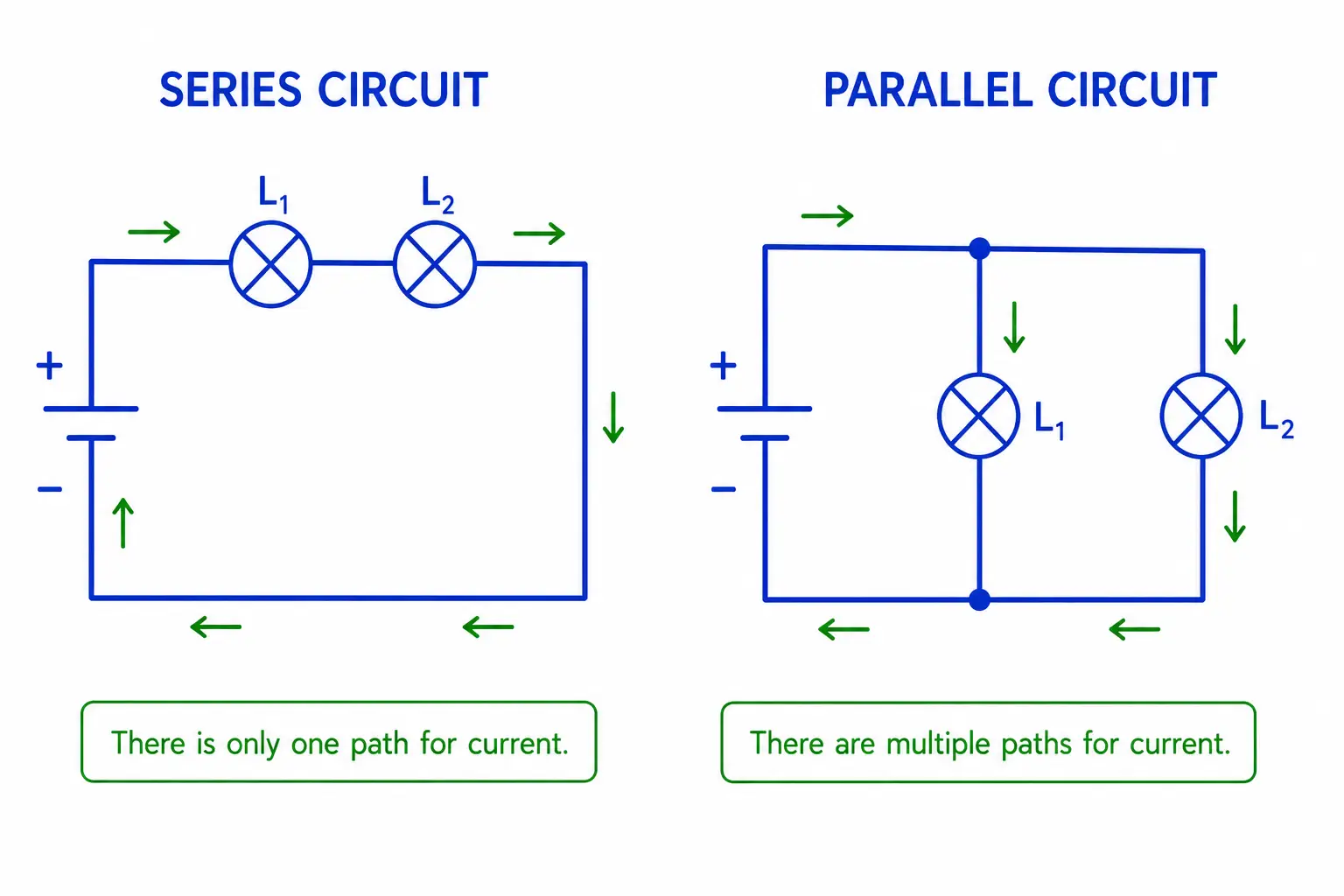
In a series circuit, there is only one path for the electricity to flow. The current will remain the same across all components, and the voltage is divided among them. The resistance increases as components are added.
If one component breaks, the entire circuit stops, because the loop has been opened.
Let’s look at an example with the resistance in a series circuit.
What is the total resistance in a series circuit if the resistors are , , and ?
For a series, we would just add them, so
.
Parallel circuits
In a parallel circuit, there are multiple paths for the electricity to flow. The current will be divided amongst the parallel branches, while the voltage stays the same across every component. The resistance decreases as components are added.
If one component breaks, the entire circuit will remain on, because the loop is still closed.
Now let’s look at an example with the resistance in a parallel circuit.
If two resistors are wired in parallel, what is the total resistance?
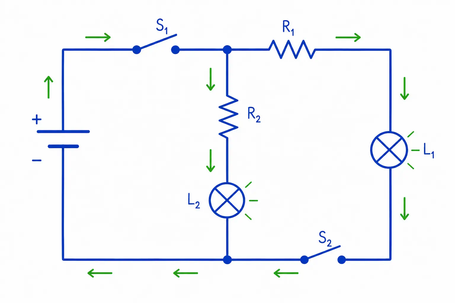
Let’s look at a more complex example that combines what we’ve learned.
This circuit has two switches and two branches. sits before the branches split, so opening it cuts power to both and .
, however, sits only in the branch with and , so opening it only turns off .
stays on, powered through the branch, since that loop is still closed.
Short circuits
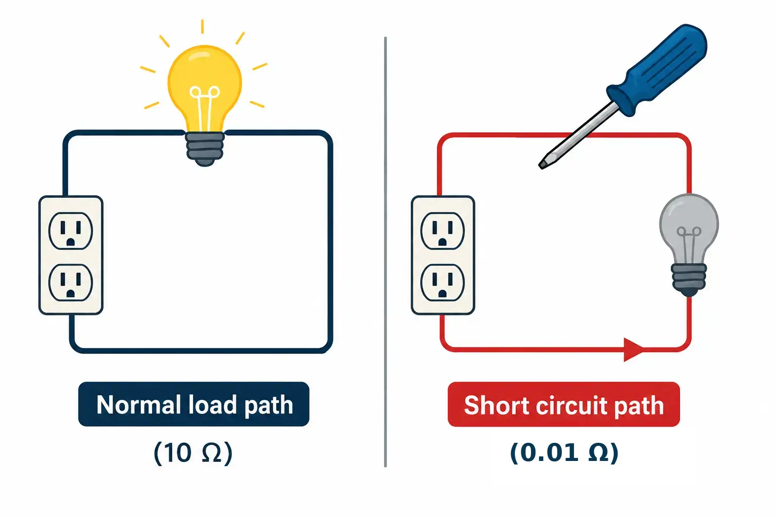
A short in a circuit is caused by electricity traveling an unintended path. Electrons will flow through the path of least resistance, so if something interferes with the intended loop, the electrons will take another route.
We can use Ohm’s Law to see exactly why this is so dangerous. In the diagram above, the normal load path has a resistance of about , while the short circuit path (created by electrons flowing through the metal screwdriver instead of through the circuit) has almost no resistance at all, about . Assuming a standard household voltage of V:
Normal path:
amps
Short circuit path:
amps
That’s a thousand-fold spike in current in an instant — more than enough to melt wires, start a fire, or destroy the device. This is exactly the kind of current spike a fuse or breaker is designed to catch before it causes damage.
Safety
Grounding
Grounding works on the same principle as shorts in circuits. Because electricity will follow the path of least resistance, we can use that knowledge to safely dissipate dangerous charges. Grounding literally uses the earth as a conductor for the electricity, away from people or equipment. A lightning rod is a familiar example: it gives a lightning strike an easy, low-resistance path into the ground instead of through a building.
Fuses and breakers
Fuses and breakers serve the same purpose: to disconnect power when the current gets too high, protecting people or equipment.
Fuses contain a small metal link that melts when the current exceeds the rated value, breaking the circuit. They are a one-time-use protection and must be replaced once “blown.”
Breakers contain a thermal strip or magnetic coil, which releases—or “trips”—when the current is overloaded. This opens the circuit and shuts off the power. Unlike fuses, breakers can usually be reset for repeated use.