



Achievable logoAchievable logo
AP Physics 1
Sign in
Sign up
Purchase
Textbook
Practice exams
Support
How it works
Exam catalog
Mountain with a flag at the peak
Textbook
Introduction
1. Decoding the exam
2. Vectors and their analysis
3. Kinematics
4. Laws of motion
5. Work, energy, and power
6. Linear momentum and collisions
7. Torque and rotational mechanics
7.1 Rotational kinematics
7.2 Torque and rotational inertia
7.3 Work and energy in rotation
7.4 Angular momentum and angular impulse
8. Oscillations
9. Fluids
Wrapping up
Achievable logoAchievable logo
7.2 Torque and rotational inertia
Achievable AP Physics 1
7. Torque and rotational mechanics
Our AP Physics 1 course is currently in development and is a work-in-progress.

Torque and rotational inertia

12 min read
Font
Discuss
Share
Feedback

In linear dynamics, a force F acting on a mass m produces an acceleration a=F/m. In rotational dynamics, torque τ plays the role of force, and the moment of inertia I plays the role of mass. The rotational analogue of Newton’s second law is

∑τ=Iα,

where α is the angular acceleration.

In this subchapter:

  • We define torque and moment of inertia
  • Develop the key theorems for computing I, and work through representative examples.

Definition of torque

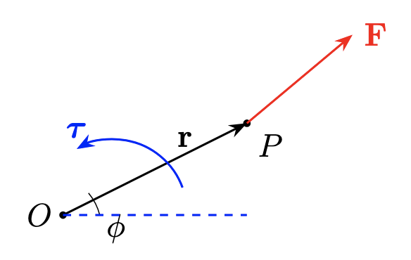
A force F applied at a point P produces a torque about an origin (pivot) O given by the cross product

τ=r×F,τ=rFsinϕ,

where:

  • r is the position vector from O to P
  • ϕ is the angle between r and F

By the right-hand rule, a positive τ corresponds to counterclockwise rotation.

Vector illustration of torque

Lever arm form. You can also write torque in terms of the lever arm (the perpendicular distance from the pivot to the force’s line of action):

τ=Fℓ,ℓ=rsinϕ,

where ℓ is the perpendicular distance (lever arm) from O to the line of action of F.

Sign conventions

Choose a right-handed coordinate system. Positive torque is the torque that, by the right-hand rule (thumb out of the page), tends to rotate the object counterclockwise about the axis.

Moment of inertia

Just as mass m measures an object’s resistance to linear acceleration (F=ma), the moment of inertia I measures a body’s resistance to angular acceleration (τ=Iα). The farther the mass is distributed from the axis, the larger I becomes.

Definitions
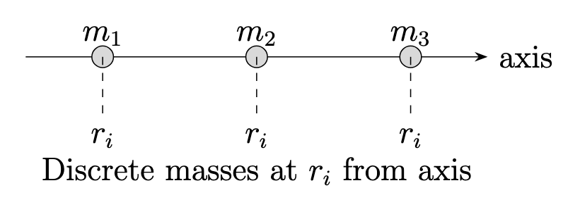
Discrete point masses
For N point masses mi​ each at perpendicular distance ri​ from the axis,

I=i=1∑N​mi​ri2​.

Moment of inertia for discrete system
Definitions
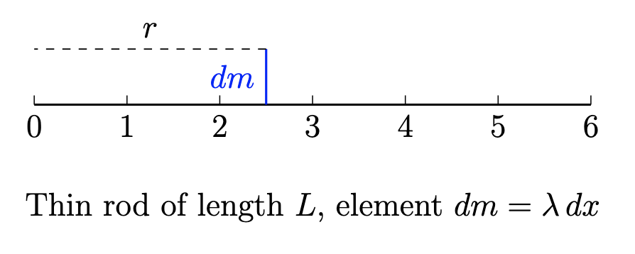
Continuous distribution
For a rigid body of total mass M with density ρ(r), (integral solving not in AP Physics 1 scope)

I=∫r2dm=∫V​r2ρ(r)dV,M=∫V​ρ(r)dV.

Moment of inertia for a rigid body

Common moments of inertia

Thin hoop or ring, radius R:Solid disk, radius R:Thin rod about center:Thin rod about end:​I=MR2,I=21​MR2,I=121​ML2,I=31​ML2.​

Parallel‐axis and shell theorems Parallel‐axis theorem

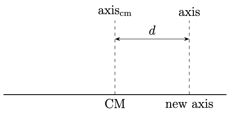
If Icm​ is the moment of inertia about an axis through the center of mass, then the moment about a parallel axis at distance d is

I=Icm​+Md2.

Parallel axis theorem

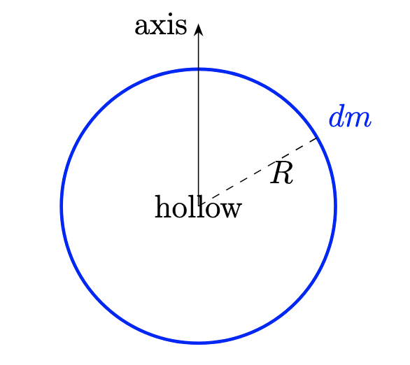
Thin cylindrical shell theorem. A thin cylindrical shell of mass M and radius R has

Ishell​=MR2.

A full solid cylinder may be built by stacking shells.

Thin cylindrical shell theorem

Reasoning Practice:

  1. A uniform solid disk and a thin hoop both have mass M and radius R. A tangential force F is applied at the rim of each to produce the same angular acceleration α. Explain which object requires a larger torque to achieve the same α, and why.

Solution: The required torque is τ=Iα. For a solid disk, Idisk​=21​MR2. For a thin hoop, Ihoop​=MR2. To get the same α, the hoop requires

τhoop​=Ihoop​α=(MR2)α,τdisk​=(21​MR2)α.

Since MR2>21​MR2, the thin hoop requires twice the torque of the solid disk to achieve the same α.

  1. A mechanic uses a wrench of length L=0.30 m to loosen a bolt by applying a force F=100 N perpendicular to the handle.

    1. Calculate the torque τ produced.
    2. If the mechanic instead uses a wrench of length L/2 and applies the same force F, how does the torque change? Discuss the reasoning in terms of lever arm and rotational inertia.

Solution: (a) When the force is perpendicular, torque is τ=rF. With r=L=0.30 m and F=100 N,

τ=(0.30 m)(100 N)=30 N⋅m.

(b) If r=L/2=0.15 m and the same F=100 N, then

τ′=(0.15 m)(100 N)=15 N⋅m.

Halving the lever arm halves the torque. The bolt’s rotational inertia is unchanged, but the applied torque is smaller, so you’d need either a larger force or a longer wrench to get the same twisting effect.

  1. A rectangular door of width w and mass m swings on hinges at one edge. Explain why applying a force near the hinges requires a larger force to generate the same torque compared to applying the force near the free edge. Relate your answer to lever arm and moment of inertia.

Solution: Torque from a force F applied a distance r from the hinge is τ=rF. Near the hinges, r is small, so to produce the same torque you must use a larger F. Near the free edge (where r=w), the same force produces a larger torque because the lever arm is larger. The door’s moment of inertia about the hinge is fixed by its geometry, so changing where you push changes the lever arm (and therefore the torque), not the door’s I.

  1. A uniform thin rod of length L and mass M rotates about its center with angular acceleration α1​ under a constant torque τ. If the same rod instead rotates about one end under the same torque τ, what will be its angular acceleration α2​? Explain the relationship between the rod’s moment of inertia in each case and the resulting angular acceleration.

Solution: When rotating about the center, Icenter​=121​ML2. Thus

α1​=Icenter​τ​=121​ML2τ​=ML212τ​.

When rotating about one end, Iend​=31​ML2. Then

α2​=Iend​τ​=31​ML2τ​=ML23τ​.

Comparing,

α2​=ML23τ​,α1​=ML212τ​,⟹α2​=4α1​​.

The rod’s moment of inertia about the end is four times larger than about its center, so the same torque produces one-quarter the angular acceleration.

Example problem 1

A uniform rod of length L=2.0m and mass M=3.0kg.

Moment of inertia across two different axes

We wish to compute:

Icm​(about midpoint axis),Iend​(about axis at one end).

Solution:

  1. Moment about the center. For a uniform rod of length L, the standard result is

    Icm​=121​ML2.

    Substituting M=3.0kg and L=2.0m:

    Icm​=121​(3.0)(2.0)2=121​×3.0×4.0=1.0kg⋅m2.

  2. Moment about one end (Parallel‐Axis Theorem). The parallel-axis theorem states

    Iend​=Icm​+Md2,

    where d is the distance from the center-of-mass axis to the new axis. Here d=2L​=1.0m, so

    Iend​=1.0+(3.0)(1.0)2=1.0+3.0=4.0kg⋅m2.

Final Answers:

Icm​=1.0kg⋅m2,Iend​=4.0kg⋅m2.

Example problem 2

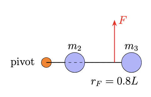
A uniform rod of mass m1​=2.0kg and length L=1.2m is pivoted frictionlessly about one end. Two small masses, m2​=1.0kg and m3​=0.5kg, are rigidly attached to the rod at distances r2​=3L​ and r3​=L, respectively, from the pivot. A force F=10N is applied perpendicular to the rod at a point rF​=0.8L from the pivot.

Uniform rod pivoted at one end with two small masses attached
  1. Compute the total moment of inertia Itot​ of the system about the pivot.
  2. Find the initial angular acceleration α of the system.

Solution:

  1. Moment of inertia.

    Irod​=31​m1​L2=31​(2.0)(1.2)2=0.96kg⋅m2,

    I2​=m2​r22​=(1.0)(31.2​)2=0.16kg⋅m2,

    I3​=m3​r32​=(0.5)(1.2)2=0.72kg⋅m2.

    Total:

    Itot​=0.96+0.16+0.72=1.84kg⋅m2.

  2. Angular acceleration. Torque due to F:

    τ=FrF​=10(0.8×1.2)=9.6N⋅m.

    Thus

    α=Itot​τ​=1.849.6​≈5.22rad/s2.

Example problem 3

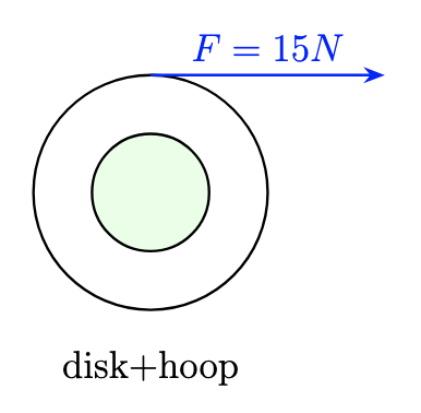
A composite wheel consists of a solid disk of mass M=3.0kg and radius R=0.20m rigidly fastened to a thin hoop of mass m=1.0kg and radius 2R=0.40m. The assembly rotates about its central axis. A string wrapped around the outer hoop exerts a constant tangential force F=15N on the hoop.

The composite wheel rotating about its central axis
  1. Determine the moment of inertia Icomp​ of the composite wheel about its axis.
  2. Find the angular acceleration α produced by the applied force.

Solution:

  1. Composite disk + hoop.

    Idisk​=21​MR2=21​(3.0)(0.20)2=0.06kg⋅m2,

    Ihoop​=m(2R)2=1.0(0.40)2=0.16kg⋅m2,

    Icomp​=0.06+0.16=0.22kg⋅m2.

  2. Angular acceleration.

    τ=F(2R)=15(0.40)=6.0N⋅m,

    α=Icomp​τ​=0.226.0​≈27.3rad/s2.

Torque\

  • Rotational analogue of force; τ=r×F
  • Magnitude: τ=rFsinϕ or τ=Fℓ (lever arm form)
  • Direction by right-hand rule; positive = counterclockwise

Sign Conventions\

  • Use right-handed coordinate system
  • Positive torque: counterclockwise about axis

Moment of Inertia (I)\

  • Rotational analogue of mass; measures resistance to angular acceleration
  • For N point masses: I=∑mi​ri2​
  • For continuous bodies: I=∫r2dm
  • I increases as mass is distributed farther from axis

Common Moments of Inertia\

  • Thin hoop/ring (radius R): I=MR2
  • Solid disk (radius R): I=21​MR2
  • Thin rod (center): I=121​ML2
  • Thin rod (end): I=31​ML2

Parallel-Axis and Shell Theorems\

  • Parallel-Axis: I=Icm​+Md2 (d = distance from center of mass axis)
  • Thin cylindrical shell: Ishell​=MR2
  • Solid cylinder: sum of shells

Reasoning Practice Takeaways\

  • Larger I → more torque needed for same angular acceleration (τ=Iα)
  • Torque increases with longer lever arm; halving lever arm halves torque
  • Applying force farther from pivot increases torque (lever arm effect)
  • Rotating about axis farther from center of mass increases I, reduces angular acceleration for same torque

Example Problem Key Results\

  • For rods: Icm​=121​ML2, Iend​=31​ML2
  • For composite systems: sum moments of inertia of all parts about same axis
  • Angular acceleration: α=τ/Itot​

Summary Concepts\

  • Torque: depends on force, distance from pivot, and angle
  • Moment of inertia: depends on mass distribution relative to axis
  • Use correct I formulas and sign conventions for rotational motion problems

Sign up for free to take 6 quiz questions on this topic

Previous
Next  | 7.3 Work and energy in rotation
All rights reserved ©2016 - 2026 Achievable, Inc.

Torque and rotational inertia

In linear dynamics, a force F acting on a mass m produces an acceleration a=F/m. In rotational dynamics, torque τ plays the role of force, and the moment of inertia I plays the role of mass. The rotational analogue of Newton’s second law is

∑τ=Iα,

where α is the angular acceleration.

In this subchapter:

  • We define torque and moment of inertia
  • Develop the key theorems for computing I, and work through representative examples.

Definition of torque

A force F applied at a point P produces a torque about an origin (pivot) O given by the cross product

τ=r×F,τ=rFsinϕ,

where:

  • r is the position vector from O to P
  • ϕ is the angle between r and F

By the right-hand rule, a positive τ corresponds to counterclockwise rotation.

Lever arm form. You can also write torque in terms of the lever arm (the perpendicular distance from the pivot to the force’s line of action):

τ=Fℓ,ℓ=rsinϕ,

where ℓ is the perpendicular distance (lever arm) from O to the line of action of F.

Sign conventions

Choose a right-handed coordinate system. Positive torque is the torque that, by the right-hand rule (thumb out of the page), tends to rotate the object counterclockwise about the axis.

Moment of inertia

Just as mass m measures an object’s resistance to linear acceleration (F=ma), the moment of inertia I measures a body’s resistance to angular acceleration (τ=Iα). The farther the mass is distributed from the axis, the larger I becomes.

Definitions
Discrete point masses
For N point masses mi​ each at perpendicular distance ri​ from the axis,

I=i=1∑N​mi​ri2​.

Definitions
Continuous distribution
For a rigid body of total mass M with density ρ(r), (integral solving not in AP Physics 1 scope)

I=∫r2dm=∫V​r2ρ(r)dV,M=∫V​ρ(r)dV.

Common moments of inertia

Thin hoop or ring, radius R:Solid disk, radius R:Thin rod about center:Thin rod about end:​I=MR2,I=21​MR2,I=121​ML2,I=31​ML2.​

Parallel‐axis and shell theorems Parallel‐axis theorem

If Icm​ is the moment of inertia about an axis through the center of mass, then the moment about a parallel axis at distance d is

I=Icm​+Md2.

Thin cylindrical shell theorem. A thin cylindrical shell of mass M and radius R has

Ishell​=MR2.

A full solid cylinder may be built by stacking shells.

Reasoning Practice:

  1. A uniform solid disk and a thin hoop both have mass M and radius R. A tangential force F is applied at the rim of each to produce the same angular acceleration α. Explain which object requires a larger torque to achieve the same α, and why.

Solution: The required torque is τ=Iα. For a solid disk, Idisk​=21​MR2. For a thin hoop, Ihoop​=MR2. To get the same α, the hoop requires

τhoop​=Ihoop​α=(MR2)α,τdisk​=(21​MR2)α.

Since MR2>21​MR2, the thin hoop requires twice the torque of the solid disk to achieve the same α.

  1. A mechanic uses a wrench of length L=0.30 m to loosen a bolt by applying a force F=100 N perpendicular to the handle.

    1. Calculate the torque τ produced.
    2. If the mechanic instead uses a wrench of length L/2 and applies the same force F, how does the torque change? Discuss the reasoning in terms of lever arm and rotational inertia.

Solution: (a) When the force is perpendicular, torque is τ=rF. With r=L=0.30 m and F=100 N,

τ=(0.30 m)(100 N)=30 N⋅m.

(b) If r=L/2=0.15 m and the same F=100 N, then

τ′=(0.15 m)(100 N)=15 N⋅m.

Halving the lever arm halves the torque. The bolt’s rotational inertia is unchanged, but the applied torque is smaller, so you’d need either a larger force or a longer wrench to get the same twisting effect.

  1. A rectangular door of width w and mass m swings on hinges at one edge. Explain why applying a force near the hinges requires a larger force to generate the same torque compared to applying the force near the free edge. Relate your answer to lever arm and moment of inertia.

Solution: Torque from a force F applied a distance r from the hinge is τ=rF. Near the hinges, r is small, so to produce the same torque you must use a larger F. Near the free edge (where r=w), the same force produces a larger torque because the lever arm is larger. The door’s moment of inertia about the hinge is fixed by its geometry, so changing where you push changes the lever arm (and therefore the torque), not the door’s I.

  1. A uniform thin rod of length L and mass M rotates about its center with angular acceleration α1​ under a constant torque τ. If the same rod instead rotates about one end under the same torque τ, what will be its angular acceleration α2​? Explain the relationship between the rod’s moment of inertia in each case and the resulting angular acceleration.

Solution: When rotating about the center, Icenter​=121​ML2. Thus

α1​=Icenter​τ​=121​ML2τ​=ML212τ​.

When rotating about one end, Iend​=31​ML2. Then

α2​=Iend​τ​=31​ML2τ​=ML23τ​.

Comparing,

α2​=ML23τ​,α1​=ML212τ​,⟹α2​=4α1​​.

The rod’s moment of inertia about the end is four times larger than about its center, so the same torque produces one-quarter the angular acceleration.

Example problem 1

A uniform rod of length L=2.0m and mass M=3.0kg.

We wish to compute:

Icm​(about midpoint axis),Iend​(about axis at one end).

Solution:

  1. Moment about the center. For a uniform rod of length L, the standard result is

    Icm​=121​ML2.

    Substituting M=3.0kg and L=2.0m:

    Icm​=121​(3.0)(2.0)2=121​×3.0×4.0=1.0kg⋅m2.

  2. Moment about one end (Parallel‐Axis Theorem). The parallel-axis theorem states

    Iend​=Icm​+Md2,

    where d is the distance from the center-of-mass axis to the new axis. Here d=2L​=1.0m, so

    Iend​=1.0+(3.0)(1.0)2=1.0+3.0=4.0kg⋅m2.

Final Answers:

Icm​=1.0kg⋅m2,Iend​=4.0kg⋅m2.

Example problem 2

A uniform rod of mass m1​=2.0kg and length L=1.2m is pivoted frictionlessly about one end. Two small masses, m2​=1.0kg and m3​=0.5kg, are rigidly attached to the rod at distances r2​=3L​ and r3​=L, respectively, from the pivot. A force F=10N is applied perpendicular to the rod at a point rF​=0.8L from the pivot.

  1. Compute the total moment of inertia Itot​ of the system about the pivot.
  2. Find the initial angular acceleration α of the system.

Solution:

  1. Moment of inertia.

    Irod​=31​m1​L2=31​(2.0)(1.2)2=0.96kg⋅m2,

    I2​=m2​r22​=(1.0)(31.2​)2=0.16kg⋅m2,

    I3​=m3​r32​=(0.5)(1.2)2=0.72kg⋅m2.

    Total:

    Itot​=0.96+0.16+0.72=1.84kg⋅m2.

  2. Angular acceleration. Torque due to F:

    τ=FrF​=10(0.8×1.2)=9.6N⋅m.

    Thus

    α=Itot​τ​=1.849.6​≈5.22rad/s2.

Example problem 3

A composite wheel consists of a solid disk of mass M=3.0kg and radius R=0.20m rigidly fastened to a thin hoop of mass m=1.0kg and radius 2R=0.40m. The assembly rotates about its central axis. A string wrapped around the outer hoop exerts a constant tangential force F=15N on the hoop.

  1. Determine the moment of inertia Icomp​ of the composite wheel about its axis.
  2. Find the angular acceleration α produced by the applied force.

Solution:

  1. Composite disk + hoop.

    Idisk​=21​MR2=21​(3.0)(0.20)2=0.06kg⋅m2,

    Ihoop​=m(2R)2=1.0(0.40)2=0.16kg⋅m2,

    Icomp​=0.06+0.16=0.22kg⋅m2.

  2. Angular acceleration.

    τ=F(2R)=15(0.40)=6.0N⋅m,

    α=Icomp​τ​=0.226.0​≈27.3rad/s2.

Key points

Torque\

  • Rotational analogue of force; τ=r×F
  • Magnitude: τ=rFsinϕ or τ=Fℓ (lever arm form)
  • Direction by right-hand rule; positive = counterclockwise

Sign Conventions\

  • Use right-handed coordinate system
  • Positive torque: counterclockwise about axis

Moment of Inertia (I)\

  • Rotational analogue of mass; measures resistance to angular acceleration
  • For N point masses: I=∑mi​ri2​
  • For continuous bodies: I=∫r2dm
  • I increases as mass is distributed farther from axis

Common Moments of Inertia\

  • Thin hoop/ring (radius R): I=MR2
  • Solid disk (radius R): I=21​MR2
  • Thin rod (center): I=121​ML2
  • Thin rod (end): I=31​ML2

Parallel-Axis and Shell Theorems\

  • Parallel-Axis: I=Icm​+Md2 (d = distance from center of mass axis)
  • Thin cylindrical shell: Ishell​=MR2
  • Solid cylinder: sum of shells

Reasoning Practice Takeaways\

  • Larger I → more torque needed for same angular acceleration (τ=Iα)
  • Torque increases with longer lever arm; halving lever arm halves torque
  • Applying force farther from pivot increases torque (lever arm effect)
  • Rotating about axis farther from center of mass increases I, reduces angular acceleration for same torque

Example Problem Key Results\

  • For rods: Icm​=121​ML2, Iend​=31​ML2
  • For composite systems: sum moments of inertia of all parts about same axis
  • Angular acceleration: α=τ/Itot​

Summary Concepts\

  • Torque: depends on force, distance from pivot, and angle
  • Moment of inertia: depends on mass distribution relative to axis
  • Use correct I formulas and sign conventions for rotational motion problems

More from Torque and rotational mechanics

  • Rotational kinematics
  • Work and energy in rotation
  • Angular momentum and angular impulse